| Tweet |

Custom Search
|
|

|
||
 TM 55-1905-223-24-1
(1) Two crankshaft revolutions are required to adjust all of the valves and injectors.
NOTE
One pair of valves and one injector are adjusted at each index mark before rotating the crankshaft to the next
mark.
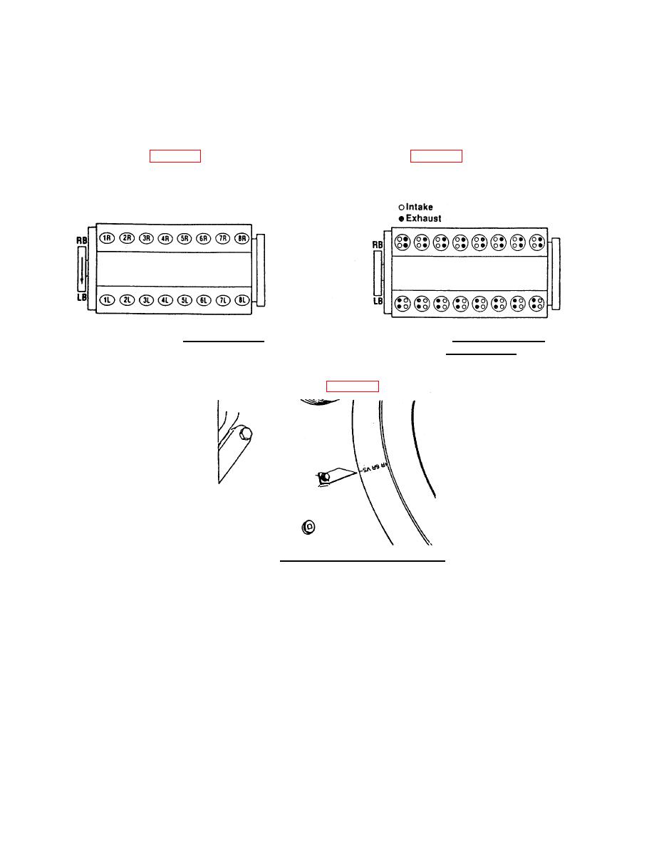
(2) Reference FIG. 2-33 for how cylinders are numbered. Reference FIG. 2-34 for location of intake and
exhaust valves.
FIGURE 2-33. Cylinder Number.
FIGURE 2-34. Intake and Exhaust
Valve Location.
(3) The KTA50 engine has valve and injector adjustment marks in three locations.
(a) Adjustment marks are on the vibration damper (FIG. 2-35). The marks must be aligned with pointer.
FIGURE 2-35. Intake and Exhaust Valve Location.
2-108
|
||
 |
||