| Tweet |

Custom Search
|
|

|
||
 TM 55-1905-223-24-1
(b) Determine the cylinder in position for valve set. The valves are ready to be adjusted on the cylinder
that has all the valves closed.
CAUTION
o
All adjusting screws must be loose on all cylinders.
O
The push rod must remain in alignment.
NOTE
Perform this step on both cylinders to be checked.
(c) Hold both rocker levers against the crosshead . Turn the adjusting screws until they touch the push
s
rods.
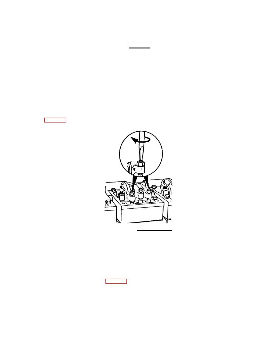
(d) Turn the lock nuts until they touch the levers. Compare the height of the adjusting screws above the
lock nut (FIG. 2-40).
FIGURE 2-40. Adjusting Screws.
(e) The cylinder that has the adjusting screws that are the same height is ready for valve adjustment.
NOTE
The push rods will be the same height above the top of the rocker lever housing on the cylinder ready for valve
adjustment.
(f) After identifying the cylinder with the valves ready to be adjusted, use the following chart for sequence.
Adjust valves to the initial set shown in FIG. 2-41.
2-111
|
||
 |
||