| Tweet |

Custom Search
|
|

|
||
 TM 55-1905-223-24-1
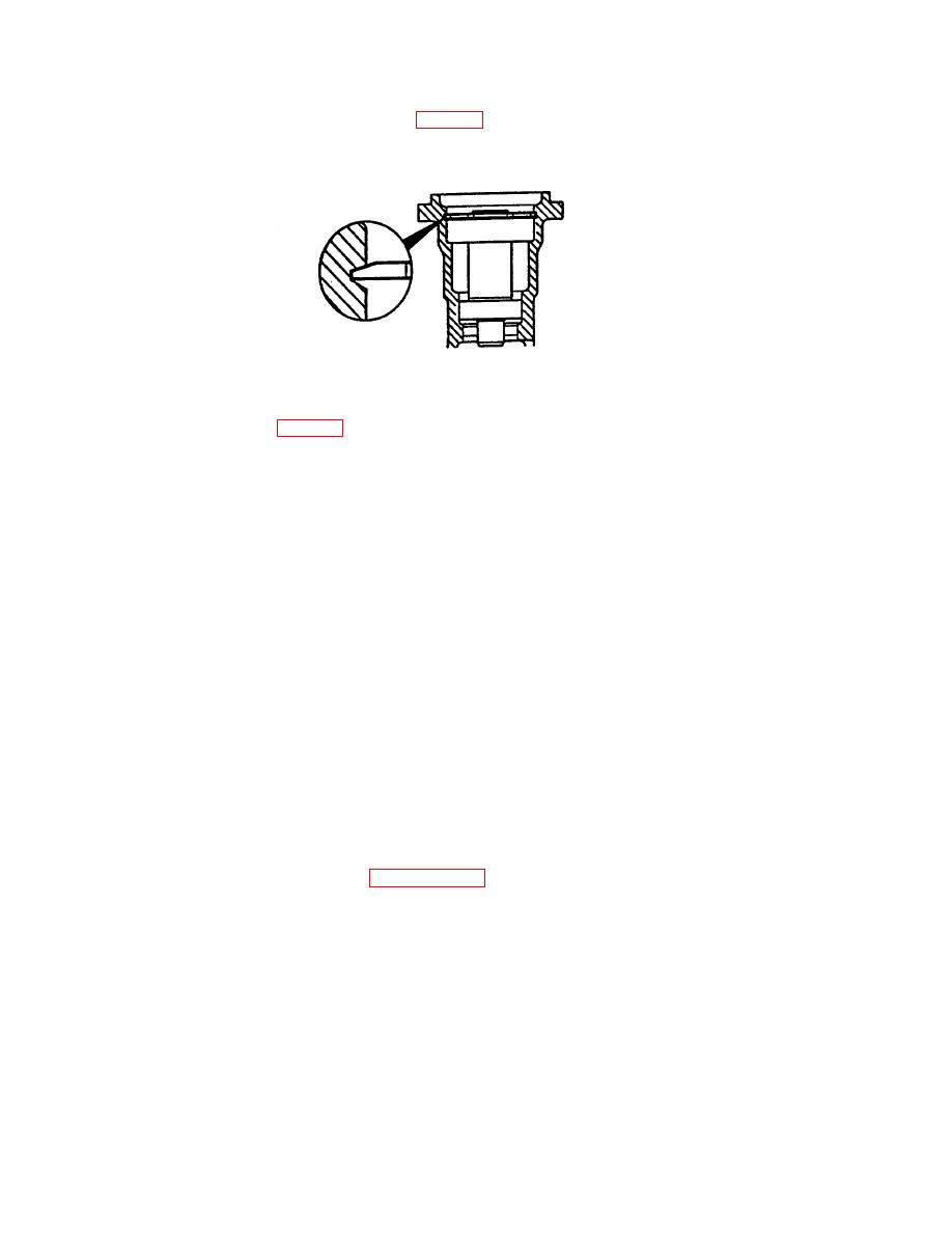
h. Use water pump bearing driver to install the shaft (4). Ensure the beveled
edge of the shaft is positioned as shown in FIG. 3-4.
FIGURE 3-4. Shaft Beveled Edge Position.
i.
Install retaining ring (3, FIG. 3-1).
CAUTION
Support the water pump body, not the shaft. This will prevent damage to the bearings.
j.
Support the water pump housing (12) with the impeller end up. Use water pump
seal driver (part number 3377260) to install the seat (10). Ensure that the
seal touches the housing and that the installed height of the seal is 0.841
inch (21.36 mm) to 0.861 inch (21.87 mm).
CAUTION
The seal will fail if the spring tension is not correct. One drop of
Loctite 290 must be applied on the joint between the seat and
the shaft. More than one drop of Loctite 290 can cause the seal
to fail.
k.
Apply one drop of Loctite 290 to the seal (10) and the parting line of the
shaft.
1. Apply thin coat of Loctite 601 to the impeller (11) bore. Supporting the
drive end of the shaft, align the slot in the impeller (11) to the slot in
the shaft and press the impeller on flush with end of the shaft.
m. Install engine cooling system pump (paragraph 2-23).
3-19
|
||
 |
||