| Tweet |

Custom Search
|
|

|
||
 TM 55-1905-223-24-1
(2) Use inside micrometer to measure the inside diameter of the crosshead guide bore in the cylinder
head (FIG. 4-33). Verify diameter is between 0.4314 and 0.4325 inch (10.958 and 10.986 mm).
CAUTION
Do not use a hammer to install the crosshead guide.
FIGURE 4-33. Crosshead Guide Bore Measurement.
(3) Install crosshead guide using crosshead guide mandrel. Verify guide is straight. Verify installed
height of guide is between 2.350 and 2.370 inch (59.69 and 60.20 mm).
g. Grind valves.
(1) Clean valve with solvent.
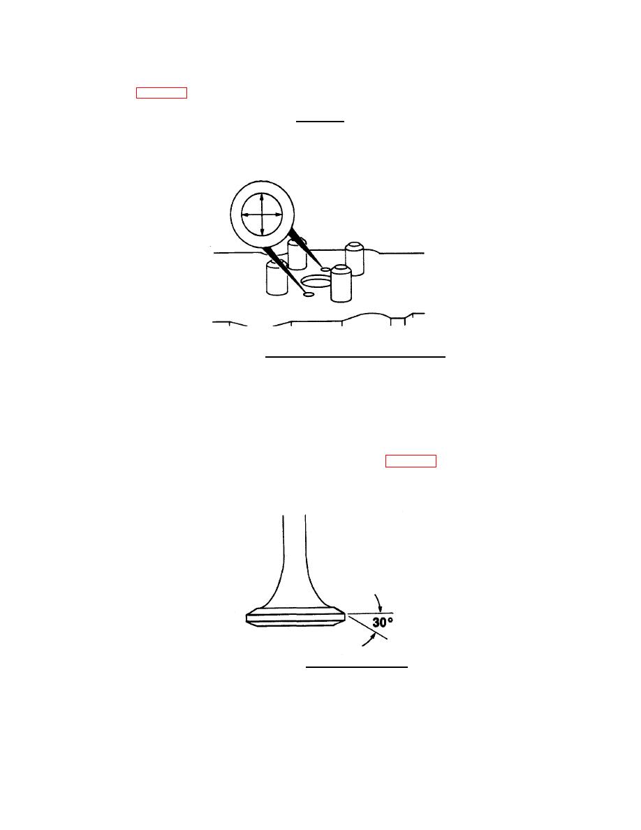
(2) Use valve facing machine to grind valve to angle shown in FIG. 4-34.
(3) Ensure intake and exhaust valves are machined to the same angle.
FIGURE 4-34. Valve Grinding Angle.
4-28
|
||
 |
||