| Tweet |

Custom Search
|
|

|
||
 TM 55-1905-223-24-1
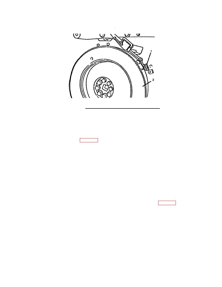
FIGURE 4-45. Vibration Damper Eccentricity Measurement.
NOTE
When adjusting the dial indicator, the indicator tip must
not touch the valve and injector adjustment marks.
(1) Mount a dial indicator (1, FIG. 4-45) to the gear cover; position the indicator pointer on a machined
surface of the outer member one-half inch back from the face of the damper (2).
(2) Rotate the engine crankshaft 360 degrees and record the total indicator runout. Verify eccentricity
does not exceed 0.020 inch (0.51 mm).
(3) If the measurement is not within specifications, ensure that the roll pin is installed correctly. If it is
still not within specifications, remove and inspect the damper.
NOTE
The crankshaft end clearance must be pushed or pulled in the
same direction each time a measurement is taken during
wobble measurement.
(4) Move the dial indicator (1) 0.50 inch (13.0 mm) from the outside diameter (FIG. 4-46).
4-41
|
||
 |
||