
| Tweet |

Custom Search
|
|

|
||
 TM 55-1905-223-24-18-1
(2) Install replacement cartridge fuse into fuse holder cap (1), insert into
fuse holder and turn fuse holder cap (1) clockwise to secure.
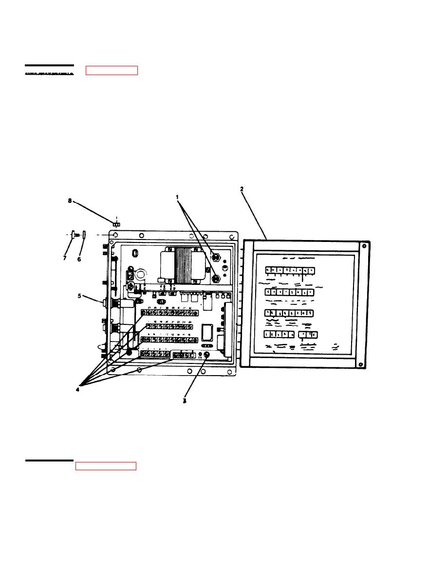
REPLACEMENT (FIGURE 2-16)
a. Replace Control Module Assembly .
(1) Attach control module assembly to bracket on second stage vessel with
machine bolts (7), lock washers (6) and plain hexagon nuts (8).
(2) Remove tags and reconnect all wiring to five terminal boards (4) and lug E9
(3) .
(3) Remove warning tag from power panel and restore power.
a. Calibrate Oil Content Alarm .
(1) Turn power switch (1) on.
|
||
|
||


