| Tweet |

Custom Search
|
|
|
|||||

|
|||||
 TM 55-1905-223-24-18-2
NOTE
Pump lock and hexhead capscrew are replaced when impeller
running clearance adjustment is completed.
g. Install pump shaft (11), impeller adjustment screw (16), annular ball bearing
(21) and pump frame (13) as a unit on motor shaft (22) and motor housing
flange (20).
h. Install four hexhead capscrews (19).
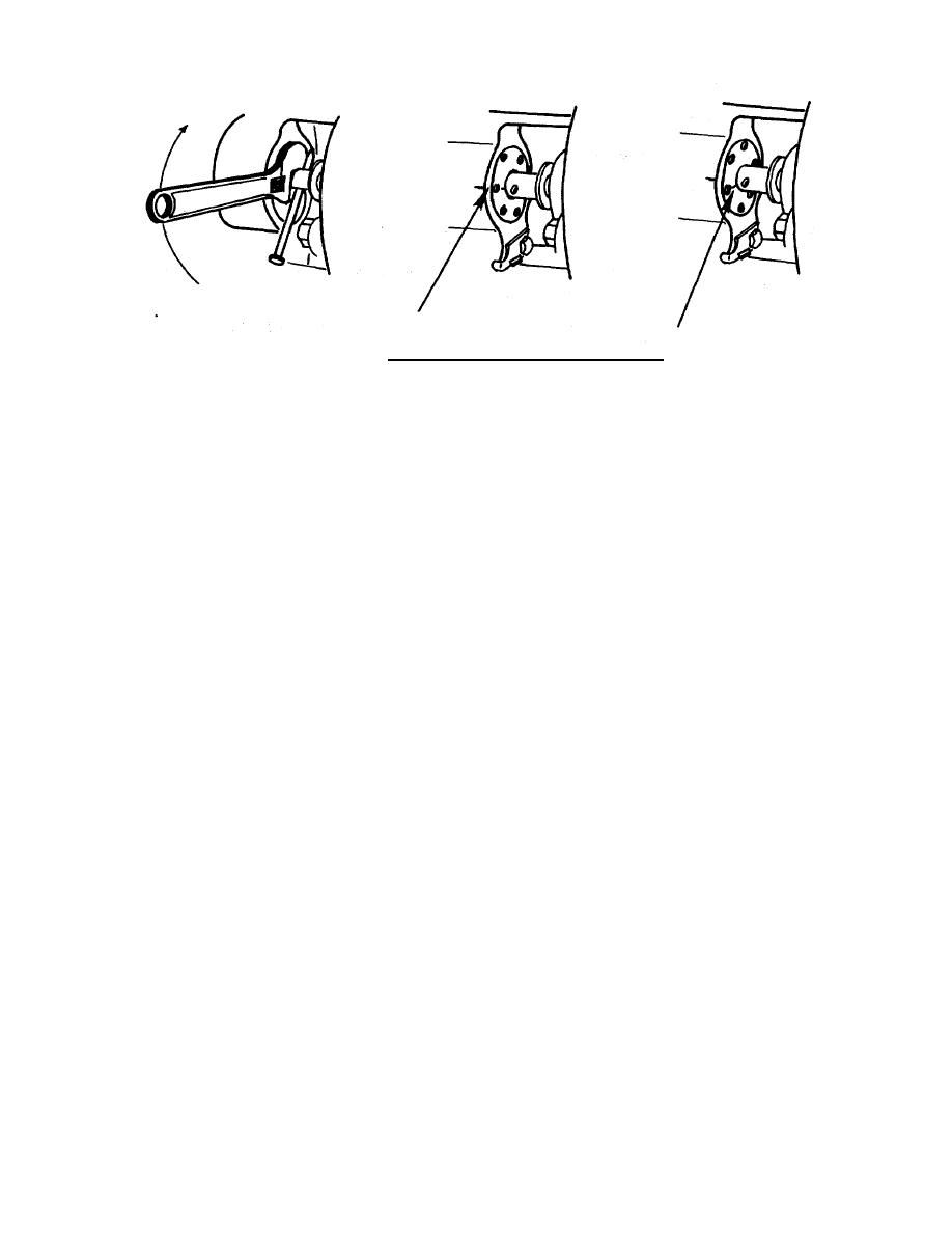
NOTE
To assist installation of centrifugal pump impeller, pump shaft is
held-stationary by placing either a screwdriver or nail of suitable
size through hole provided on the close coupled pump shaft.
i. Install screwdriver or nail through hole in pump shaft (11).
j. Install plain seal (14).
k. Install preformed packing (4).
l. Install key (12).
m. Install impeller (10).
n. Install hex plain nut (9).
o. Install pump raceway (6).
p. Install two machine screws (7).
q. Install rubber bushing (5).
3-387
|
|||||
 |
|||||