
| Tweet |

Custom Search
|
|

|
||
 TM 55-1905-223-24-3
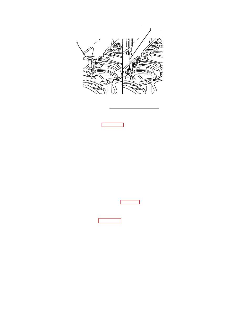
FIGURE 2-38. Tightening Adjusting Screw.
(d)
Hold the adjusting screw in this position. The adjusting screw must not turn when the lock
nut is tightened (refer to Figure 2-36). Tighten the lock nut to the following value:
- 35 ft-lb (45 N ) torque.
With adapter
m
- 45 ft-lb (60 N ) torque.
Without adapter
m
(e)
After tightening the lock nut to the correct torque valve, ensure the feeler gauge will silde
backward and forward between the crosshead and the rocker lever with only a slight drag.
(f)
If using the feel method, attempt to insert a feeler gauge that is 0.001 inch (0.03 mm)
thicker between the crosshead and the rocker lever pad. The valve lash is not correct when
a thicker feeler gauge will fit.
(g)
After adjusting the injector on cylinder No. 3 and the crossheads and the valves on
cylinder No. 5, rotate the accessory drive and align the next valve set mark with the
pointer.
(h)
Adjust the appropriate injector, the crossheads, and the valves following the Injector and
Valve Adjustment Sequence Chart, Table 2-3.
(i)
Repeat the process to adjust all injectors, crossheads, and valves correctly.
h. Install a new valve cover gasket (9, Figure 2-23) on each rocker lever housing (18).
2-126
|
||
|
||


