| Tweet |

Custom Search
|
|

|
||
 TM 55-1905-223-24-3
(c)
The crankshaft rotation is clockwise when viewed from the front of the engine.
(d)
The cylinders are numbered from the front gear cover end of the engine.
(e)
The engine firing order is 1-5-3-6-2-4.
(f)
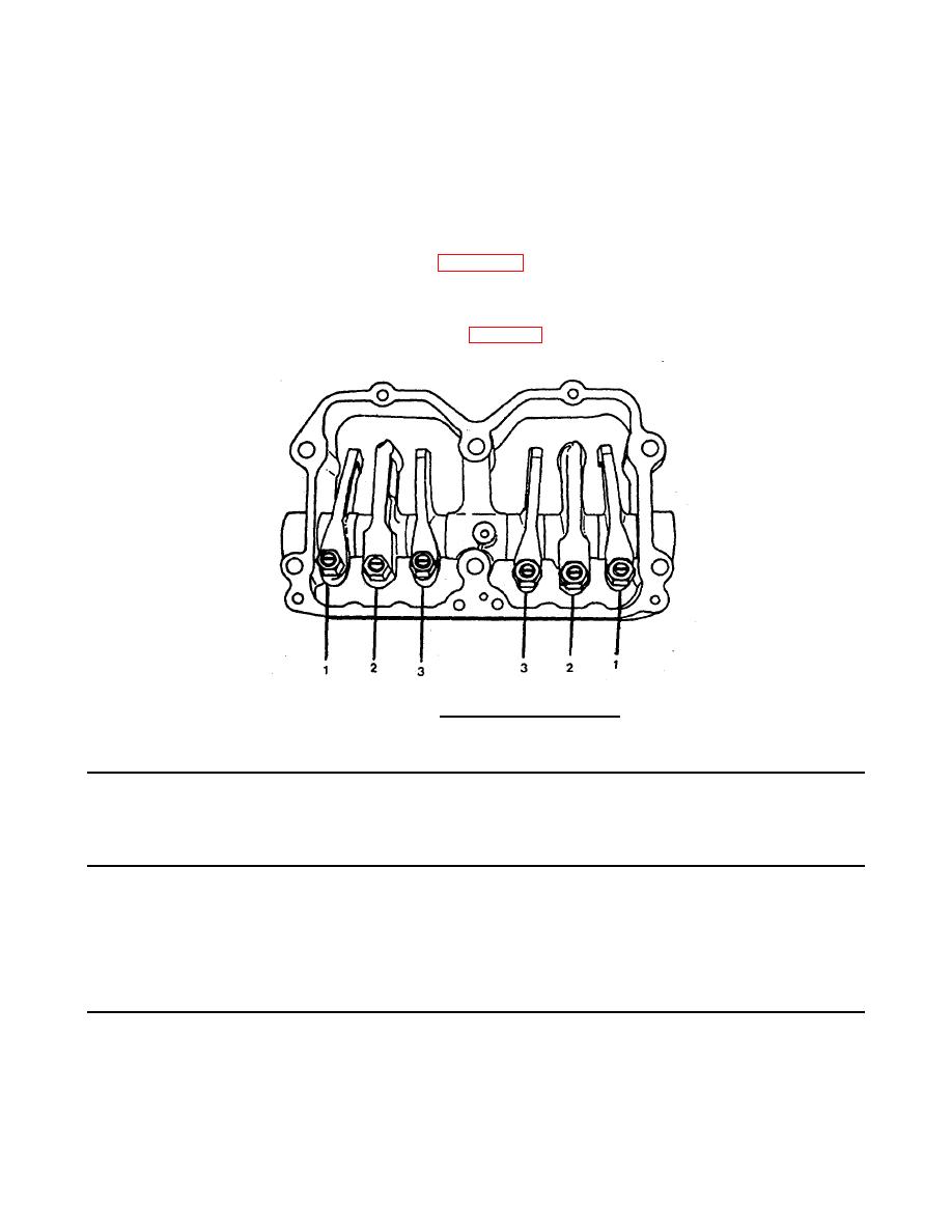
Each cylinder has three rocker levers. The rocker lever nearest to the center of the
housing is the intake lever (3, Figure 2-30), the exhaust lever is (1), and the injector lever is
(2).
(g)
The valves and the injectors on the same cylinder are not adjusted at the same index mark
on the accessory drive pulley (see Table 2-3).
FIGURE 2-30. Identifying Rocker Levers.
Table 2-3. Injector and Valve Adjustment Sequence
Bar Engine
in Direction
Pulley
Set Cylinder
of Rotation
Position
Injector
Valve
Start
A
3
5
Advance to
B
6
3
Advance to
C
2
6
Advance to
A
4
2
Advance to
B
1
4
Firing Order: 1-5-3-6-2-4
C
5
1
2-117
|
||
 |
||