| Tweet |

Custom Search
|
|

|
||
 TM 55-1905-223-24-3
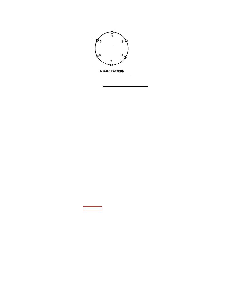
FIGURE 3-10. Coupling Torque Sequence.
l.
If a gap remains between the generator feet and the subbase crossmember after relieving all tension
on the hoist, add shims as necessary to close the gap.
m. Remove the hoist from the generator.
n. Install the mounting bolts in the generator feet to fasten it to the crossmember.
o. Tighten the mounting bolts in the generator feet.
p. Tighten the mounting bolts in the generator feet.
q. Check the air gap between the exciter rotor and the exciter stator as follows:
NOTE
Access the rotor through the housing openings.
(1) Insert a .010 inch (.254 mm) feeler gauge between the exciter rotor and the exciter stator.
(2) Run the feeler gauge around the rotor.
(3) Gap must be at least .010 inch (.254 mm) al the way around the rotor.
(4) If the gap is less than .010 inch on any side, the generator must be realigned.
r.
Install the weather screens (5, Figure 3-8) to each side of the housing (6) with screws (4).
s.
With the terminal box cover removed, run all cables, wiring, and conduits to, and through, the same
locations on the generator terminal box that they were removed from on the old generator assembly.
Refer to tags and notes that were make on the removal process.
3-28
|
||
 |
||