| Tweet |

Custom Search
|
|

|
||
 TM 55-1905-223-24-5
j. Apply a light coat of Loctite to the bore in the drive pulley (34). Push the water pump shaft (39) into
the bore until the pulley (34) is against the larger diameter (shoulder) of the shaft (39).
k. Apply a light coat of Loctite to the bore in the impeller (30). Support the pulley end of the shaft (39).
Push the impeller (30) onto the shaft (39). The clearance between the vanes of the case iron impeller
(30) and the housing must be 0.020 to 0.040 inch (0.51 mm to 1.02 mm), if not, pump must be
replaced.
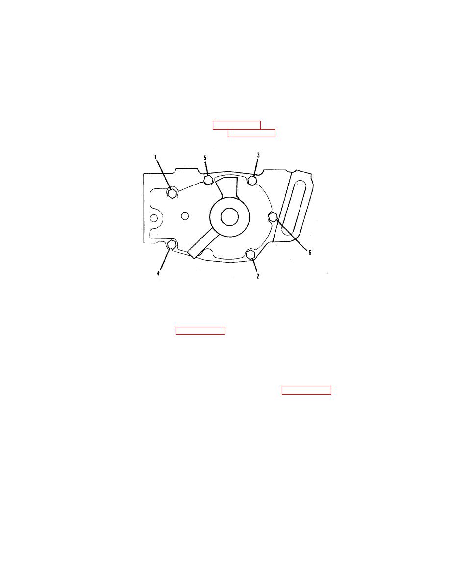
1. Install water pump with six capscrews (17, FIGURE 2-21, Sheet 1). Tighten in stages in 10 ft-lbs, and
20 ft-lbs and 35 ft-lbs in the sequence shown in FIGURE 2-22.
FIGURE 2-22. Bolt-Tightening Sequence.
m. Install gasket (22), plate (21) and capscrews (20) to cylinder block. Torque to 35 ft-lb.
n. Install preformed packing (24, FIGURE 2-21, Sheet 3) and, connect water bypass pipe (23). Install
pipe retaining clamp (26) and tighten with capscrew (25).
o. Connect water filter hose (16).
p. Install water pump V-belt (19) on the pulley (18).
q. Loosen idler pulling locknut (14). Install adjusting screw (13, FIGURE 2-21, Sheet 1) and increase
tension by turning clockwise.
r. Tighten idler pulley locknut (14) and washer (15) to 50 ft-lbs torque.
s. Turn adjusting screw 1/2 turn counterclockwise to prevent breakage.
t. Mount bracket (9) to pump and secure with capscrews (6, 10) and washers (7, 8).
u. Install belt guard (5), and hexhead capscrew bolts (2), lockwashers (3) and flatwashers (4).
v. Add coolant to engine and test.
2-92
|
||
 |
||