| Tweet |

Custom Search
|
|

|
||
 TM 55-1905-223-24-5
(3) Install the assembled washer screws (15, FIGURE 3-13).
NOTE
The longer capscrews are used to secure the engine lifting brackets.
(4) Install the engine lifting brackets (10, 11) with hexagon head capscrews (9).
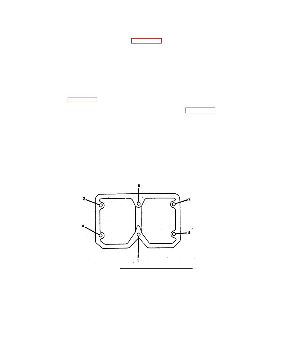
(5) Tighten the housing and bracket screws (9 and 15) to 60 ft-lb. (81.3 N ) torque. Use the sequence
m
shown in FIGURE 3-18 when tightening the housing assembled washer screws.
n. Repeat steps k through m for the two remaining rocker lever housings (14, FIGURE 3-13).
o. Adjust crossheads, valves, and injectors as follows:
NOTE
The crossheads, valves, and injectors must be adjusting at the same time. Use
the following procedure for adjusting.
FIGURE 3-18. Rocker Housing Torque Sequence.
3-32
|
||
 |
||