| Tweet |

Custom Search
|
|

|
||
 TM 55-1905-223-24-5
NOTE
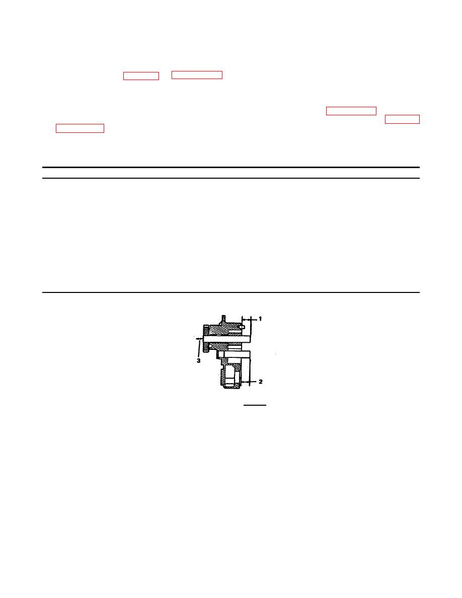
See Table 3-5 and FIGURE 3-68 for the correct idler shaft protrusion after it is
installed in the pump body.
d. Apply a coat of lubricating oil to the inside diameter of the driven gear (27, FIGURE 3-64). Install the
gear (27) onto the drive shaft (30). Use an arbor press to push the gear (27) onto the shaft (30). See Table 3-5
and FIGURE 3-68 to find the correct amount of protrusion .the drive shaft must have after the gear is installed.
Table 3-5. Oil Pump Shaft Limits - Inch (mm)
Minimum
Maximum
Single Oil Pump
Drive Shaft
Protrusion 1
0.855
0.875
(21.72)
(22.22)
Idler Shaft
Protrusion 2
0.720
0.740
(18.29)
(18.80)
Drive Shaft End
0.0002
0.0005
3 Movement
(0.05)
(0.13)
SINGLE
FIGURE 3-68. Limits.
e.
Install the drive shaft (30) from the gear pocket side of the pump body, into the bore in the pump body
(31). Apply a coat of lubricating oil to the inside diameter of the drive gear(s) (34). Put the gear (34)
on the shaft (30) on the side of the body opposite to the gear pockets; use an arbor press to push the
gear (34) onto the shaft (30). There must not be-more than 0.012 inch (0.030 mm) clearance between
the gear (34) and the body (31).
3-107
|
||
 |
||