
| Tweet |

Custom Search
|
|

|
||
 TM 55-1905-223-24-5
h.
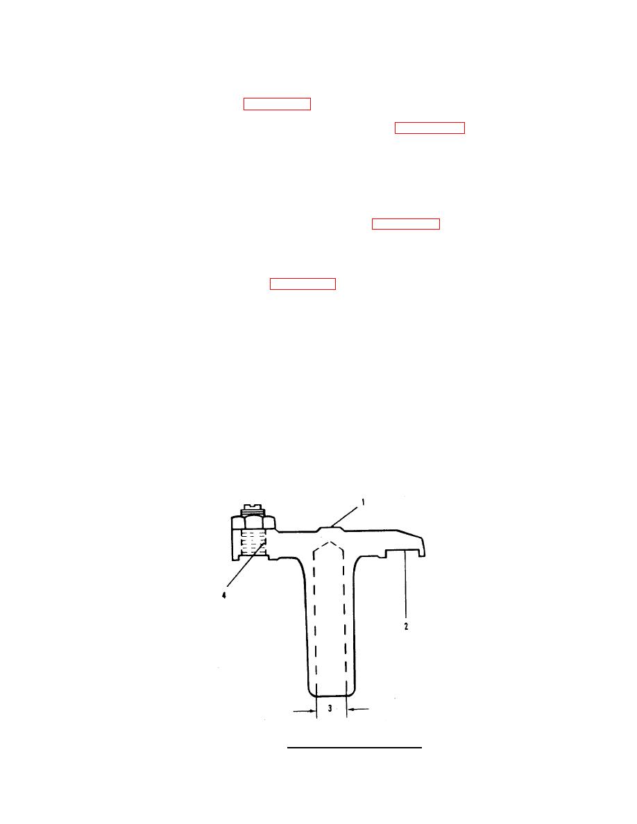
Crossheads and guides. Inspection and replacement.
(1)
Crossheads (21, FIGURE 4-1).
(a)
Check the inside diameter of the bore (3, FIGURE 4-10), replace the
crosshead if the bore exceeds 0.440 inch (11.18 mm).
(b)
Use a bore gauge to check the bore at two points spaced 90 degrees
apart to find if the bore is out-of-round. Replace as required.
(c)
Inspect the rocker lever contact surface (1) and the valve stem contact
surface (2) for wear. Check the adjusting screw and threads in the
crosshead (4) for wear or damage (FIGURE 4-10).
(d)
Replace the crosshead if there is damage to the threads in the
crosshead.
(2)
Crosshead Guides (4, FIGURE 4-1).
(a)
Make sure the guide is straight. Replace any guide that is not
straight.
(b)
Use a micrometer to measure the outside diameter of the crosshead
guide. The diameter must not be worn to less than 0.432 inch (10.97
mm). Replace as required.
(c)
The guide must be at a right angle to the surface of the cylinder head.
Replace the guide if it is not.
(d)
Use the crosshead guide spacer to install the crosshead guide.
(e)
If guide spacer is not available use a press to install the crosshead
guide. Make sure the height of the guide is between 1.860 to 1.880
inch (47.24 to 47.75 mm) after it is installed.
FIGURE 4-10. Crosshead Inspection Areas.
4-20
|
||
|
||


