| Tweet |

Custom Search
|
|

|
||
 TM 55-1905-242-14
UNIT MAINTENANCE
FOR LANDING CRAFT, MECHANIZED (LCM-8) (ALL VESSELS WITH MOD 2 APPLICATION)
BLACK WATER DISCHARGE PUMP, REPLACE
INITIAL SETUP:
Tools and Special Tools:
Personnel Required:
Tool Kit, Mechanic's Rail and Marine
Two Watercraft Engineers, 88L
(Item 1, Table 1, WP 0230 00)
Multimeter (Item 2, Table 1, WP 0230 00)
Material/Parts:
Suitable Drain Pan
Gloves, Chemical Protective (Item 3, Table 2, WP 0230 00)
Apron, Chemical Protection (Item 11, Table 2, WP 0230 00)
Equipment Condition:
BLACK WTR DISC PUMP circuit breaker set
References:
to OFF, locked out, and tagged out IAW
FM 55-502
FM 55-502
FM 55-509-1
TM 55-1905-242-24P (0135)
REMOVAL
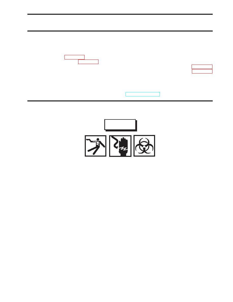
WARNING
Replace or repair components only after the affected circuit has been secured, locked
out, and tagged out. Performing replacement with the circuit energized may result in
damaged equipment and serious injury or death to personnel.
Sewage is a common mode of transmission for parasitic organisms that may have the
capability of causing communicable diseases. Protective gloves and a protective apron
should be worn to help prevent contact with sewage. After coming in contact with
sewage or contaminated equipment, be sure to clean yourself with a disinfectant soap.
Avoid sewage contact with skin abrasions, punctures, cuts, and other open wounds.
Wipe up and clean any spills and/or contaminated equipment using a disinfectant soap.
Failure to comply could result in illness, serious injury, or death.
1.
Position a suitable drain pan beneath the work area.
2.
Cut the wires (1) approximately 6 inches from the motor (2).
3.
Set the multimeter to the Vdc (Volts direct current) setting. Place one multimeter lead on each of the wire ends cut in
step 2. If no voltage is noted, proceed to the next step. If voltage is noted, ensure that the circuit breaker is properly
secured.
4.
Position the inlet and discharge valves (3 and 4) as shown in the illustration.
5.
Loosen the hose clamps (5) securing the piping (6) to the pump (7), discharge valve (4), and inlet valve (3).
6.
Remove the mounting bracket (8) securing the piping (6) and slide the piping off the pump (7) and discharge valve (4).
7.
Remove the bolts (9), nuts (10), and washers (11) securing the pump (7) to its foundation.
0135 00-1
|
||
 |
||