| Tweet |

Custom Search
|
|

|
||
 TM 55-1905-242-14
0146 00
REMOVAL (continued)
2.
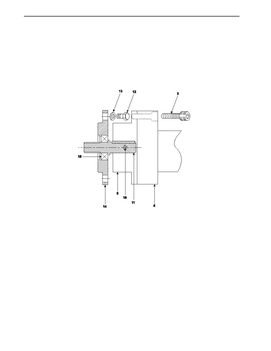
Remove the bolts (3) that secure the pump drive shaft (4) to the engine flange (5) and to the pump flange (6). Remove the
pump drive shaft.
3.
Remove the screws (7) that secure the aft and aft inboard sound insulation panels (8 and 9). Remove the insulation
panels.
4.
Remove the three set screws (10) that secure the engine flange (5) to the intermediate shaft (11) and remove the engine
flange.
5.
Remove the bolts (12) and washers (13) that secure the bearing housing (14) to the front of the engine and remove the
bearing housing, bearing (15), and intermediate shaft (11) as an assembly.
6.
Use pliers to remove the dowel pins (16) from the PTO support brackets (17).
7.
Loosen, but do not remove, the PTO support bracket bolts (18) that secure the PTO support brackets (17) to the engine
block.
8.
Remove the bolts (19) that secure the drive hub (20) in the drive coupling (21).
9.
Set the multimeter to the Vdc (Volts direct current) setting. Open the fire pump electric clutch junction box and connect
one multimeter lead to each of the clutch's wires (22). If no voltage is noted, proceed to the next step. If voltage is noted,
ensure that the circuit breaker is properly secured.
NOTE
Cotter pins, lockwashers, locking nuts, and similar locking devices shall be discarded after removal and replaced with
new cotter pins, lockwashers, locking nuts and similar locking devices.
10. Remove the clutch housing bolts (23) and lockwashers (24) that secure the clutch housing (25) to the PTO support
brackets (17) and slide the clutch housing and clutch assembly (26) out as a unit.
11. Remove the bolts (27) that secure the drive hub (20) to the clutch assembly (26). Remove the drive hub from the clutch
assembly.
0146 00-2
|
||
 |
||