| Tweet |

Custom Search
|
|

|
||
 TM 55-1905-242-14
0146 00
REMOVAL (continued)
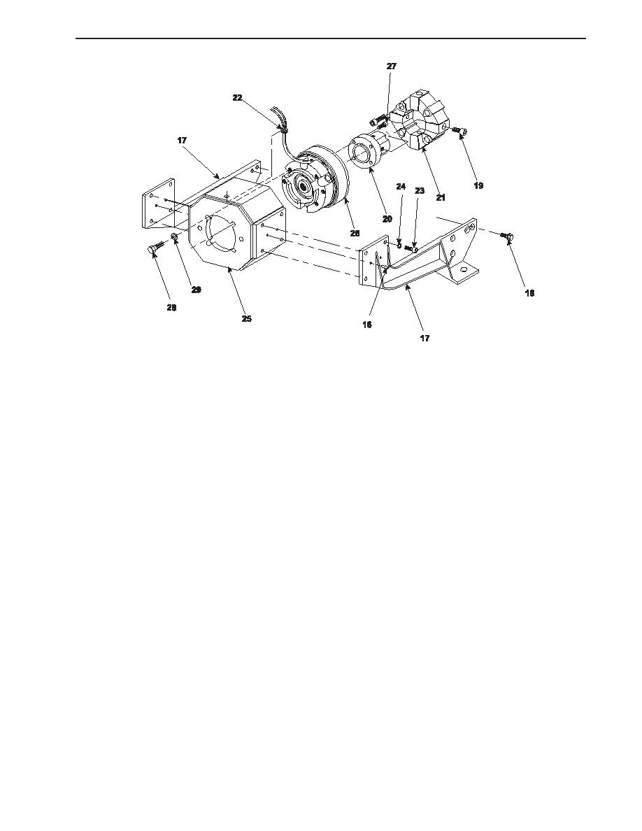
12. Remove the bolts (28) and washers (29) that secure the clutch assembly (26) to the clutch housing (25). Remove the
clutch assembly from the clutch housing.
INSTALLATION
1.
Position the clutch assembly (26) in the clutch housing (25) and secure it with the bolts (28) and washers (29).
2.
Position the drive hub (20) in the clutch assembly (26) and secure it with the bolts (27).
3.
Position the clutch housing (25) between the PTO support brackets (17) and loosely install the clutch housing bolts (23)
and lockwashers (24). The clutch housing should still be free to move at this point.
4.
Line up the holes for the dowel pins (16) and install the dowel pins. Leave enough dowel pin protruding from the PTO
support brackets (17) to allow later removal. Tighten the clutch housing bolts (23) only after installing all of the dowel
pins.
5.
Install and tighten the bolts (19) that secure the drive hub (20) in the drive coupling (21).
6.
Tighten the PTO support bracket bolts (18).
7.
Position the bearing housing (14)/bearing (15)/intermediate shaft (11) assembly to the clutch housing (25) and secure it
with the bolts (12) and washers (13).
8.
Position the engine flange (5) on the intermediate shaft (11) and secure it with the three set screws (10).
9.
Install the sound insulation panels (8 and 9) and secure them with the screws (7).
10. Install the pump drive shaft (4) between the engine flange (5) and the pump flange (6) and secure it with the bolts (3).
11. Position the pump drive shaft guard (2) on the deck plates and secure it with the bolts (1).
12. Remove the lockouts and tagouts and check the operation of the system.
END OF WORK PACKAGE
0146 00-3/4 blank
0146 00-3
|
||
 |
||