| Tweet |

Custom Search
|
|

|
||
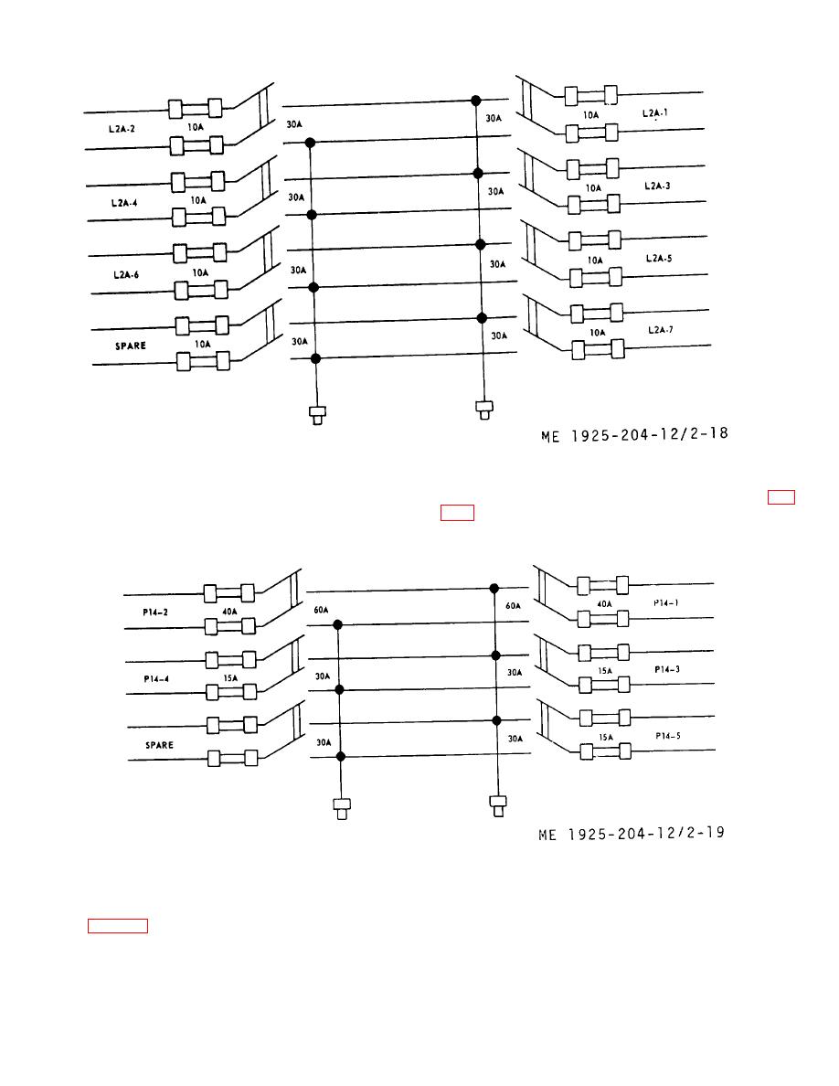
 Figure 2-18. Pilothouse lighting control panel wiring diagram.
fuses are provided in the panel for circuits supplied (fig.
(4) The ventilating power control panel, located
in the engine room, is supplied from main electrical
control panel by circuit P14. Individual switches and
Figure 2-19. Ventilating power control panel wiring diagram.
d. Battery Charging Control Panel Operation.
provide a means of charging the general alarm batteries
(1) The purpose of the battery charging cont ol
r
without disconnecting batteries from the alarm circuit.
panel (fig. 2-20), located in the upper engine room, is to
2-41
|
||
 |
||