| Tweet |

Custom Search
|
|

|
||
 TM 55-1925-204-12
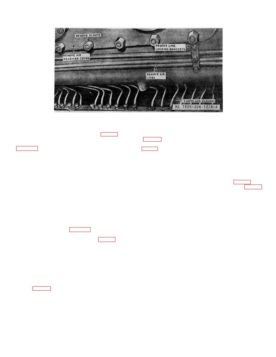
Figure 4-4. Air receiver (box) removal
(5) Disconnect the cylinder lubricating tubes.
d.
Installation.
(6) Remove 8 nuts and washers (fig. 4-4), then lift
(1) Install the cylinder sleeve and scraper rings
the cylinder off the upper base.
(7) Remove the cylinder sleeve and scraper rings
(2) Install a new cylinder to upper base gasket (4,
(8) Remove other cylinders in a similar manner.
(3) Install the new cylinder. Be sure that the
c. Cleaning, Inspection, and Repair.
cylinder is in perfect alignment by placing a long straight edge
(1) Clean the exhaust and air inlet ports. Check the
across the machined surfaces of the air receiver and exhaust
exhaust port bridge for a slight growth. Check with a thickness
flanges of the new cylinder and adjacent cylinders. Both air and
gage and a straight edge. If any growth has occurred, the port
exhaust sides must be checked, especially if the cylinder being
bridges must be stoned, or ground even to the original cylinder
replaced is on the end.
bore. A slight relief of 0.001 to 0.002 inch will do no harm.
(4) Install the 8 washers and nuts (fig. 4-4) and
Round the edges of the ports to a radius of approximately 1/16
tighten them evenly and securely to the torque given in table 1-1
inch.
(1,500 to 1,550 ft lbs).
(2) Check the water jacket for formation of scale.
(5) Continue by reversing the procedures in steps
Scrape and wash with a solvent, then rinse, and blow dry.
(1) through (5) in b. above.
Check surfaces of cylinder flange where it meets the upper
(6)
Install remaining cylinders in a similar
base. Be sure that the flange is clean, and free of burrs. Give
manner.
cylinder bore, and all machined surfaces a light coat of
lubricating oil. Wipe away any surplus oil with a dry cloth.
4-14. Air Starting System
(3) Check the cylinder for wear, against tolerances
a. General. The air start system consists of the piping
established and shown in table 1-3. Replace a defective
and engine starting mechanism. Air piping is arranged so
cylinder.
compressor air discharges into storage tanks (reservoirs).
(4) Examine the zinc post (20, fig. 3-8) for wear
Moisture is trapped in the tanks and may be released through
and errosion. Replace a defective zinc post.
the air tank drain valve. This lessens the chance of moisture
(5) Examine the water cooling tubes (27) for signs
getting into the engine. The engine is
of leaking. Replace defective water cooling tubes. Be sure and
use new gaskets (18) under each one.
NOTE
If a new cylinder and sleeve is to be
installed, be sure upper base mounting
surface and the cylinder flange are free of
burrs. And, install new rings on the piston
4-10
|
||
 |
||