| Tweet |

Custom Search
|
|

|
||
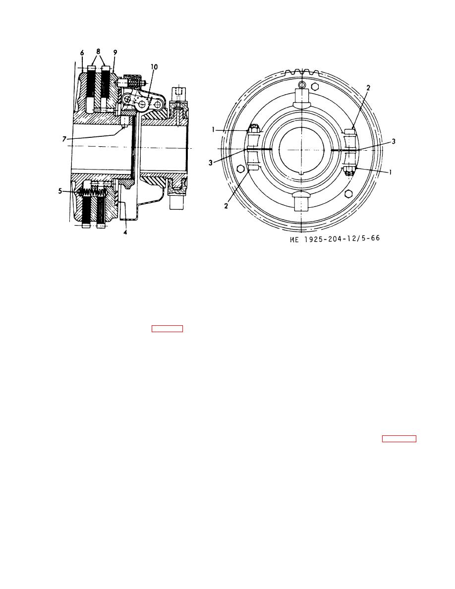
 1.
Nut
6.
Hub and backplate
2.
Bolt
7.
Setscrew, dog point
3.
Shim
8.
Lining, friction
4.
Thrust washer
9.
Plate, clutch floating
5.
Spring
10.
Yoke assembly
Figure 5-66. Clutch arrangement (Model CL208)
to prevent excessive leakage around the pump shaft. The
c. Disassembly.
pump is designed with imposed suction impellers providing
(1) Remove floating clutch plate (9, fig. 5-66) and thrust
hydraulic balance, thereby eliminating all thrust strain on
washer (4).
bearings. The prime mover drives the pump by means of a
(2) Remove springs (5), and friction linings. (8).
twin disc clutch.
d. Inspection.
Inspect the friction linings for wear.
b. Maintenance and Adjustment. The pump packing
Replace friction linings that are badly worn.
gland allows a slow water leak, when the pump is running, to
e. Reassembly.
provide lubrication between shaft and pump packing. Should
(1) Position friction linings (8), then install springs (5).
packing leak excessively, leakage may be slowed by
(2) Install the floating clutch plate (9) and thrust washer
tightening packing gland nuts while the pump is running.
(4).
Tighten only enough to bring leakage to a slow drip. Do not
f. Installation. Install by reversing the procedure in b.(1)
stop leakage entirely.
through (4) above.
c. Removal.
(1) To remove bearings, it is necessary to remove the
5-31. Fire and Salvage Pump
bearing housing from the pump.
a.
General. The fire and salvage pump has a 5-inch
(2) Remove bearing housing cover (1, fig. 5-67) by
suction and a 4-inch discharge. Adjustable packing glands
removing capscrews.
are installed in the pump housing
5-87
|
||
 |
||