| Tweet |

Custom Search
|
|

|
||
 disconnect pigtail from panel, remove cotter pin (15), cup
(b)
Energize circuit, push START button and
washer and contact spring (14), and lift off contact. Replace
observe voltage reading when accelerating contactor closes.
in reverse order of removal.
This contactor should close at 70 percent of line voltage.
Adjust to this valve with adjusting nut (8, fig. 5-82).
(2)
Replacement of contacts as follows:
NOTE
(a)
To replace stationary contact (2), remove
Contacts should be replaced in sets and
nut and screw (3) and lift off contact. Replace in reverse order
aligned to see that contacts meet squarely.
of removal.
(b)
To replace movable contact (1):
(c)
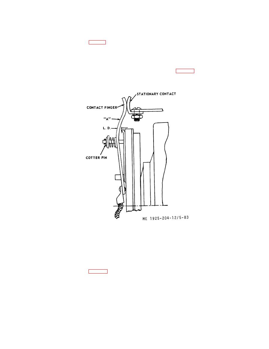
After contacts are replaced, check "Lead
Dimension" (L.D.) (fig. 5-83). This dimension should be 1/16
inch, and can be obtained by bending the movable contact at
"A."
Figure 5-83. Lead dimensions.
(3)
Coil replacement as follows:
(e)
Remove screw (6) from back of panel and
(a)
Remove external wiring connections from
lift coil (13) and core (7) from panel.
panel.
(f)
Slip coil from core.
(b)
Remove four mounting bolts and lift panel
from enclosure.
NOTE
(c)
Disconnect electrical connections from
If coil has been overheated, check all parts
coil.
for deposits of melted insulation that
(d)
Remove hairpin (12, fig. 5-82) and shaft
might
interfere
with
operation
of
(10). This permits
armature (11) to swing away from front of
contactor, and remove such deposits.
coil (13).
(g)
Replace coil in reverse order of removal.
5-111
|
||
 |
||