
| Tweet |

Custom Search
|
|

|
||
 TM 55-1905-217-34
(b) Check resistance between slip rings (E and F) (installed on rotor) with an ohmmeter (fig. 4-4).
Resistance should be 14 to 18 ohms. If resistance is low, it indicates a short between windings. Very high
resistance indicates an open winding. Replace defective rotor assembly.
(c) Check resistance between each rotor slip ring (5 or 6) and rotor frame (7) with an ohmmeter.
Resistance should be very high or indicate open circuit. If resistance is low, winding is shorted and rotor
assembly must be replaced.
(d) Check resistance between brush terminals (8 and 9, fig. 4-4) and brush holder (12).
Ohmmeter should indicate open circuit or very high resistance. If there is no or low resistance, replace brush
assembly.
(e) Check resistance between brush terminal 8 and brush 10 (fig. 4-4). Ohmmeter should
indicate very low resistance (near zero). f resistance is high, replace brush assembly. Perform same test
between brush terminal 9 and brush 11.
(f) Check resistance of isolation diodes with ohmmeter. This can be done with diodes installed
in heat sink. Disconnect lead wires and check each diode separately. Each diode should indicate a high
resistance in one direction and low resistance in other direction (ohmmeter leads reversed). Replace defective
isolation diode(s).
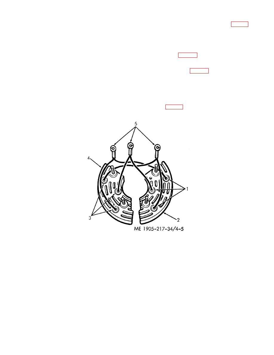
(g) Check negative rectifier diodes with an ohmmeter (fig. 4-5). Connect negative (-) ohmmeter
probe to diode heat sink (2) and positive ( +) probe to each diode (1) terminal. Resistance should be low or
zero. If resistance is high, diode is defective.
Figure 4-5. Rectifier diode test points (hulls 8500-8519 and 8520-8539).
(h) Check negative rectifier diodes as specified in (g) above but with ohmmeter leads
reversed. Resistance should be high or infinite. If resistance is low, diode is defective.
(i) Check positive rectifier diodes with an ohmmeter.
4-9
|
||
|
||


