
| Tweet |

Custom Search
|
|

|
||
 TM 55-1905-217-34
Connect positive (+) probe to diode heat sink (4) and negative (-) probe to each diode. (3) terminal. Resistance should be
low or zero. If resistance is high, diode is defective.
(j) Check positive rectifier diodes as specified in (i) above but with ohmmeter leads reversed. Resistance
should be high or infinitive. If resistance is low, diode is defective. Replace all faulty diodes.
j. Cleaning, Inspection, and Repair (Hulls 8540-8560 and 8580-8619).
(1) Wipe grease seals with a clean cloth to remove foreign material and old lubricant.
CAUTION
Do not soak grease seal in solvent.
(2) Inspect grease seals for damage. Repack seals 2/3 full of suitable ball bearing grease.
CAUTION
Do not overpack grease seals.
(3) Place ball bearings into solvent to remove dirt and old lubricant. Allow to air dry.
(4) Repack bearings with suitable grease ensuring that grease is forced out of opposite side.
CAUTION
Do not overpack ball bearings
(5) Clean metal parts in solvent, Inspect parts for damage.
(6) Inspect rear housing for damage. If bearing surface is severely damaged or worn in excess of 1.58 inch
diameter, replace housing. Replace O-ring on rear bearing retainer (34, fig. 4-2).
(7) Inspect brush and capacitor assembly. Replace assembly if length of remaining brush is less than 1/4 inch.
Test capacitor with ohmmeter-should not show continuity after initial meter deflection. Clean assembly if brushes are not
being replaced.
(8) Wipe off stator and rotor windings with a clean cloth.
CAUTION
Do not use compressed air to clean or dry rotor or stator windings.
k. Testing (Hulls 8540-8560 and 8580-8618).
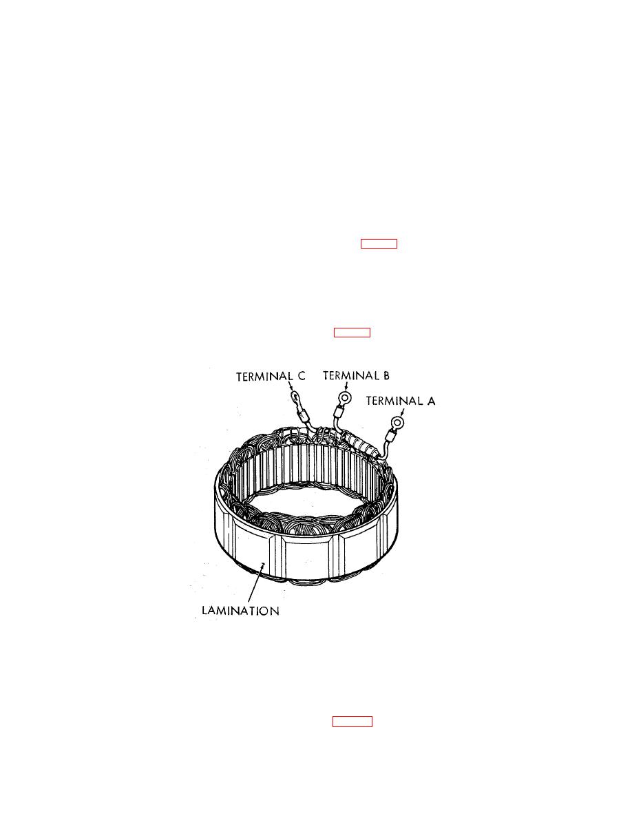
(1) Using ohmmeter, check stator terminals A, B, and C (fig. 4-6) for continuity. Continuity should exist between
terminals A and B, B and C, and A and C. Check for no continuity between the stator terminals and the stator laminations.
Replace stator if correct indications are not received.
Figure 4-6. Alternator stator testing (hulls 8540-8560 and 8580-8618).
(2) Test rotor winding as follows:
(a) Measure resistance between slip rings. Resistance should be between 15.0 and 16.0 ohms.
If resistance is low, a short is indicated between the windings. If the resistance is high, an open winding is
indicated. In either case, the rotor must be replaced.
(b) Measure resistance between each rotor slip ring and the rotor shaft. The ohmmeter should
indicate an open circuit or very high resistance. If no or low resistance is indicated, the winding is shorted and
the rotor must be replaced.
(3) Test the field diode assembly as follows (refer to fig. 4-7):
4-10
|
||
|
||


