
| Tweet |

Custom Search
|
|

|
||
 TM 55-1905-223-24-1
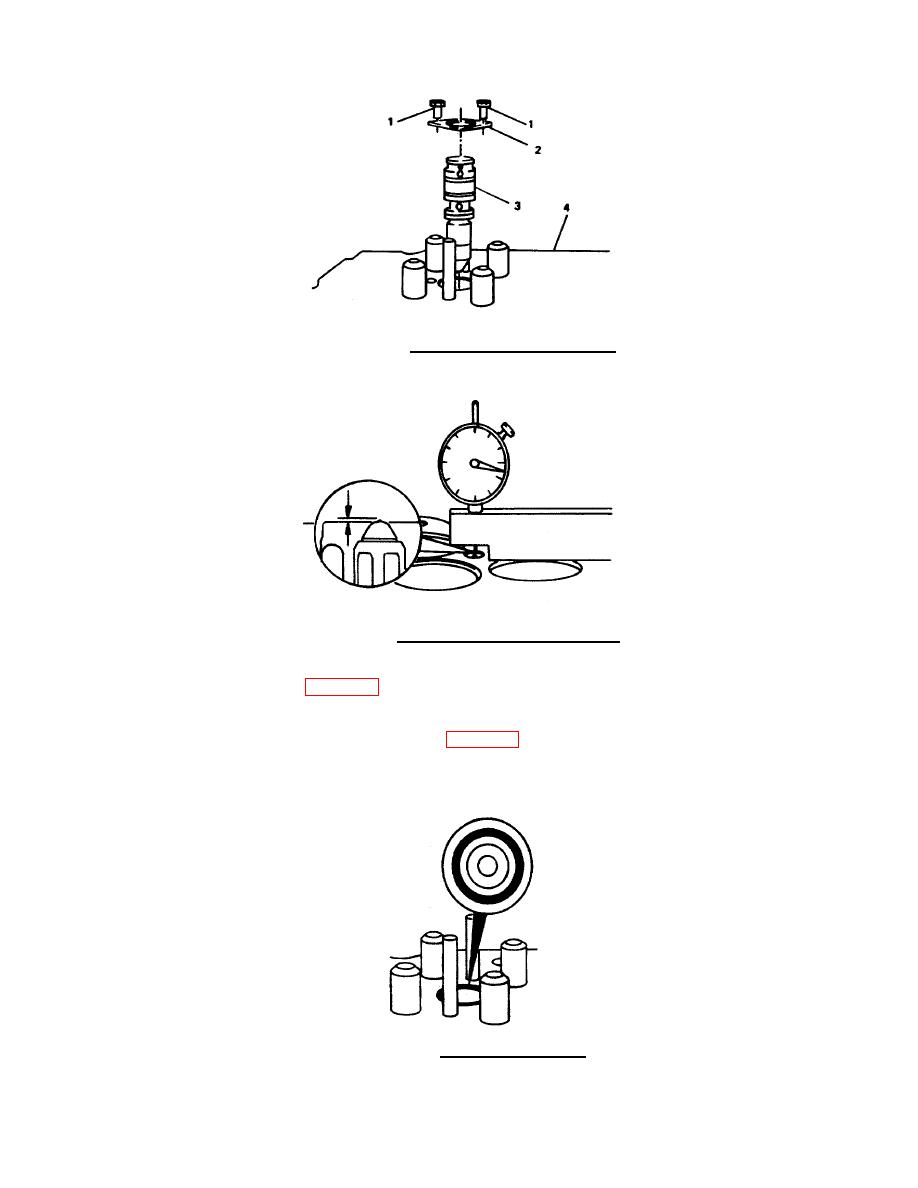
FIGURE 4-17.
Injector Removal/Replacement.
FIGURE 4-18. Injector Protrusion Measurement.
(i) Return cylinder head (4, FIG. 4-17) to original position. Remove capscrews (1), hold down clamp
(2), and injector (3).
(j) Check the contact pattern in the injector bore (FIG. 4-19). A blue band at least 0.060 inch (1.52
mm) wide and 360 degrees full circumference must be visible. If pattern is not to specifications, clean
bore with a tapered brush and recheck. If the pattern is still not to specifications, replace the cylinder
head.
FIGURE 4-19.
Prussian Blue Pattern.
4-18
|
||
|
||


