
| Tweet |

Custom Search
|
|

|
||
 TM 55-1905-223-24-3
(f)
Raise the indicator (6) approximately 0.025 inch (0.653 mm), and tighten the thumbscrew
(3) to hold the indicator in position.
WARNING
The injector plunger is under spring tension. Do not allow the tool to slip. Personal injury can result.
(g)
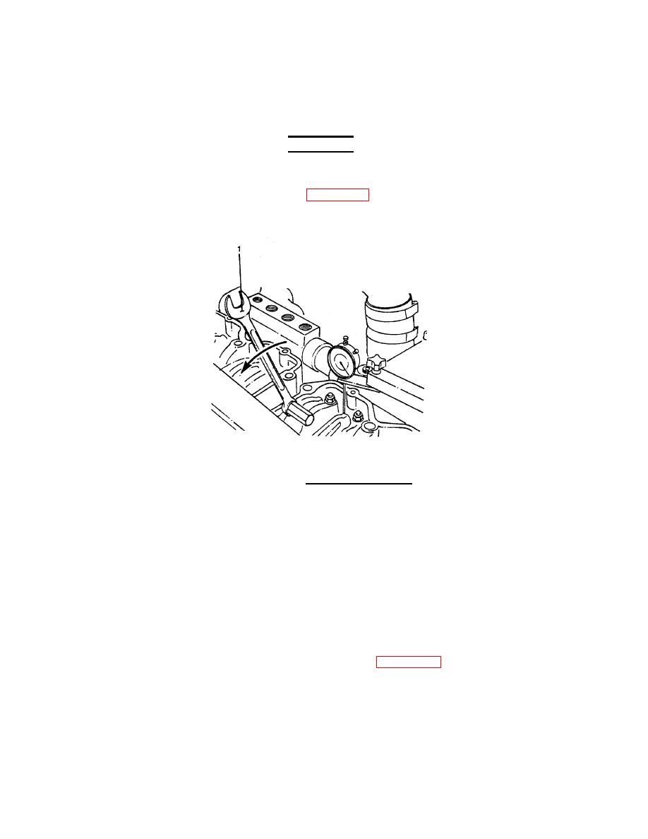
Use the rocker lever actuator (1, Figure 2-33) to depress the injector plunger three or four
times to make sure all the oil and fuel have been removed from the injector assembly.
Allow the lever to return slowly to prevent damage to the dial indicator.
FIGURE 2-33. Rocker Lever Actuator.
(h)
Actuate the lever again, and set the dial indicator at "0" (zero) while holding the injector
plunger to the bottom of its travel.
(i)
Slowly release the actuator and check the indicator travel.
(j)
The indicator travel should be between 0.226 inch and 0.230 inch. If not within those
limits, go to step (k).
(k)
Loosen the lock nut on the injector adjusting screw.
(l)
Turn the adjusting screw clockwise or counterclockwise to adjust the injector plunger to
0.228 inch.
(m)
Hold the adjusting screw in this position. See Figure 2-34. The adjusting screw must not
turn when the lock nut is tightened. Tighten the lock nut to the following value:
- 35 ft-lb (45 N ) torque.
With adaptor
m
- 45 ft-lb (60 N ) torque.
Without adaptor
m
120
|
||
|
||


