
| Tweet |

Custom Search
|
|

|
||
 (a) Insert front end of camshaft into the
11 ounces, the idler gear and bearing assembly are
opening on blower side of the engine block. Push the
satisfactory for use
camshaft into block until cam gear teeth almost engage the
10. Remove spring scale, cord and
teeth of the idler gear. Use care, and avoid damage to the
stick. Remove steel plate from face of gear.
cams.
(5) Installation.
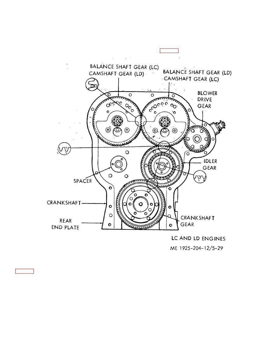
(b) Align the timing marks on the mating
gears (fig. 5-29), then slide the camshaft gear into place..
Figure 5-29. Gear train and timing marks. L. H. rotation.
(c) Secure the camshaft rear bearing (17,
(f) Install the front end cam and balance
and capscrews (4). The camshaft gear may be turned to
shaft bearings. Do not hammer bearings into cylinder block,
accommodate the capscrews through the holes in the gear
or the thrust washers may be dislodged. Secure the bearings
web. Tighten the capscrews to a torque of 35-40 ft. lbs.
with lockwashers (5) and capscrews (4). Tighten to a torque
(d) Install the balance shaft in a similar
of 35-40 ft. lbs.
manner.
(g) Apply grease to the steel face of the
(e) Apply grease to the steel face of each
remaining thrust washers (6 and 27) and install them so that
thrust washer (6 and 27). Then place one against the thrust
the steel faces are against the front end bearings (3 and 26).
shoulder (31) of each shaft, making sure the steel face is
(h) Turn
the
camshaft
intermediate
toward the front end bearings.
bearings until the holes in the bearings line up with the
5-34
|
||
|
||


