| Tweet |

Custom Search
|
|

|
||
 TM 5-2805-261-13
4.
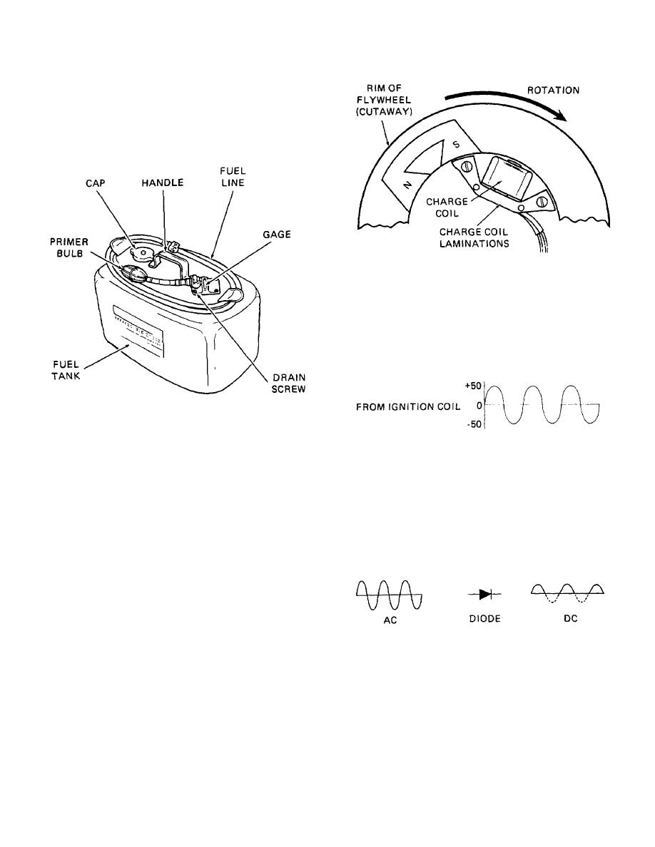
The fuel tank has a capacity of six gallons and
is portable. Attached to the tank is a bulb
primer for priming the fuel pump, fuel hose and
connector, a bracket arrangement to hold the
fuel line when it is not in use, a handle, and a
vent assembly in the filler cap. It also has a
gage to show amount of fuel in the tank.
Figure 1-11. Diagram A
The coil of insulated wire wound around the middle leg of the
laminations is affected by this fluctuating magnetism. This
results in an electric current being set up in the coil.
Because the magnetism is alternating between North and South
polarity, the current is also alternating between positive and
negative. Diagram B illustrates the alternating current (AC).
Figure 1-10. Fuel tank
C. IGNITION SYSTEM. The ignition system provides the
spark needed to ignite the air/ fuel mixture in the
Figure 1-12. Diagram B
cylinders. It is a capacitor discharge system which
means the charge of electricity is generated by
This coil current is routed through wires into the power pack
magnets in the flywheel rotating past the charge coil.
where it will be stored temporarily in a capacitor. A capacitor,
The initial electrical charge is generated by the
however, will not store alternating current. Inside the power
operator using the manual starter.
pack is a diode which is an electronic device that allows current
to flow in only one direction. In other words, it only allows the
1.
The magnets have North and South magnetic
positive current to pass. Diagram C illustrates what happens
poles and the charge coil laminations have three
when the AC is passed through a diode. Only the positive
legs. Each time one of the magnetic poles
portion of the current remains. The capacitor will accept this.
passes one of the legs of the charge coil, the
laminations become magnetized. When the
opposite pole of the magnet passes the same
leg, the magnetism in the laminator collapses
and reverses polarity. As you can see from
diagram A, the magnets keep on rotating past
all three legs of the ignition coil. Therefore, this
changing magnetism in the coil laminations
Figure 1-13. Diagram C
reverses three times in one pass of a magnet.
The capacitor in the power pack will hold this charge until it's
released. Here's how that takes place:
1-8
|
||
 |
||