| Tweet |

Custom Search
|
|

|
||
 TM 5-2805-261-13
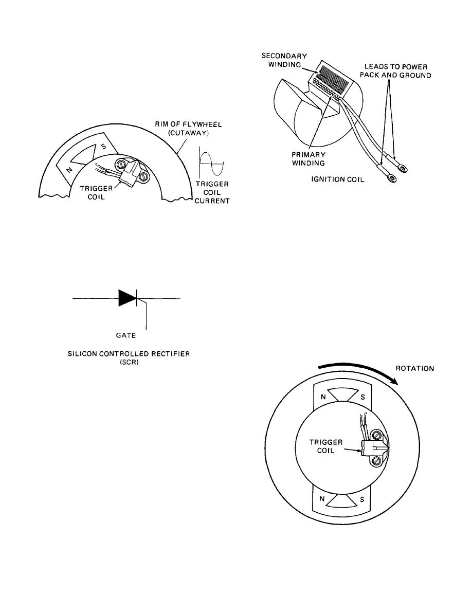
The trigger coil is located on the armature plate opposite the
charge coil. (Diagram D) It has only one point of close
proximity to the spinning magnets (the charge coil had three).
When a magnet passes this coil, an electric current is
generated but not repeated three times as with the charge
coil. This current or "trigger pulse" is also routed by wires to
the power pack.
Figure 1-16. Diagram F
The capacitor charge flows through the primary winding and
Figure 1-14. Diagram D
sets up a magnetic field in the core of the ignition coil. When
the charge has dissipated, the magnetic field in the core
Another electronic device inside the power pack, called an
breaks down. As it does so, the magnetic field passes
SCR, receives the trigger pulse. (Diagram E) An SCR is an
through the secondary windings setting up a current in them.
electronic switch. When the trigger pulse is applied to its
Since the secondary coil has many turns of wire for the field to
"gate," the SCR allows the charge, which has been stored in
pass through, the voltage established is very high.
the capacitor, to pass out of the power pack.
The high tension lead from the ignition coil carries this high
voltage current to the spark plug where it jumps the spark gap
and ignites the fuel/air mixture in the cylinder.
Since this 40-horsepower outboard has two cylinders, it must
have two spark plugs and also has two ignition coils. The
charge for the capacitor must be routed to the proper coil at
the proper time. This timing decision is made by magnetic
polarity.
Figure 1-15. Diagram E
Once the SCR has been "turned on," the capacitor releases its
charge very rapidly. This charge-discharge process can be
compared to that of a spring. A spring may be compressed
slowly, but when released, its energy is expended almost
instantly.
The burst of electrical energy from the capacitor is routed
through wires from the power pack to an ignition coil.
Ignition coils are a form of electrical transformer. (See
Diagram F) They consist of a primary winding and a
secondary winding encapsulated around an iron-laminated
core. The primary winding consists of a few turns of heavy
gage wire and the secondary winding has many turns of fine
gage wire.
Figure 1-17. Diagram G
1-9
|
||
 |
||