| Tweet |

Custom Search
|
|

|
||
 TM 55-1905-217-34
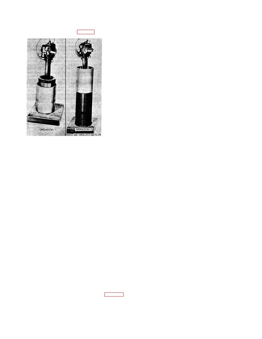
(d) Start the top of the piston straight into the ring compressor. Then, push the piston down until it contacts the
wood block ("Operation 1 " of fig. 3-79).
NOTE
The numbers on the side of the connecting rod and cap identify
the rod with the cap and indicate the particular cylinder in which
they are used. If a new service connecting rod is to be installed,
the same identification number must be stamped in the same
location as on the connecting rod that was replaced.
(e) Push the piston and connecting rod assembly down into the liner until
the piston is free of the ring compressor.
CAUTION
Do not force the piston into the liner. The peripheral abutment
type expanders apply considerable more force on the oil ring
than the standard expander. Therefore, extra care during the
loading operation must be taken to prevent ring breakage.
(f) Remove the connecting rod cap and the ring compressor. Then, push
the piston down until the compression rings pass the liner ports.
(2) Cylinder Liner, Piston and Connecting Rod Assembly. After the piston
and connecting rod assembly have been installed in the cylinder liner, the
entire assembly may then be installed in the engine as follows:
Figure 3-79. Installing piston and connecting
rod assembly in cylinder liner.
(a) If any of the pistons and liners are already in the engine, use holddown clamps, J 21793, to
retain the liners in place when the crankshaft is rotated.
(b) Rotate the crankshaft until the connecting rod journal of the particular cylinder being worked
on is at the bottom of its travel. Wipe the journal clean and lubricate it with clean engine oil.
(c) Install the upper bearing shell (the one with a short oil groove at each parting line) in the
connecting rod. Lubricate the bearing shell with clean engine oil.
(d) Hold the piston, connecting rod, and liner in line with the block bore so the identification
numbers on the connecting rod face the blower side of the engine, and the matchmarks on the liner and
the block are in alignment. Carefully guide the end of the connecting rod into the block bore so the
bearing shell will not be dislodged. Then, slide the piston, connecting rod, and liner assembly into the
block bore until the liner flange rests against the insert in the counterbore in the block.
(e) Push or pull the piston and connecting rod into the liner until the upper bearing shell is
firmly seated on the crankshaft journal.
(f) Place the lower bearing shell (the one with the continuous oil groove from one parting line to
the other) in the connecting rod bearing cap, with the tang on the bearing shell in the notch in the bearing
cap. Lubricate the bearing shell with clean engine oil.
(g) Install the bearing shell and cap on the connecting rod with the identification numbers
adjacent to each other. Tighten the connecting rod bolt nuts to 60-70 ft-lb. torque.
(h) Check the connecting rod side clearance. The clearance must be .006 inch to .012 inch.
(i) Install the remaining liner, piston and rod assemblies in the same manner.
(j) After all of the liners and pistons have been installed, remove the holddown clamps.
(k) Install the compression gaskets and water and oil seals prior to reassembling the cylinder
head to the cylinder block. (para 3-13). 3-22. Crankshaft Pulley, Vibration Damper and Front Oil Seal
a. General. The front oil seal is pressed into the crankshaft front cover and the lip of the seal bears against the
vibration damper inner cone. If oil
3-109
|
||
 |
||