| Tweet |

Custom Search
|
|

|
||
 TM 55-1905-217-34
should leak past the seal, the seal must be replaced.
b. Removal. If necessary, the front oil seal may be removed without removing the front cover. Proceed as follows:
(1) Remove the front power take-off (out-board engine only).
(2) Remove bolt and washer from end of crankshaft. Partially reinstall the bolt.
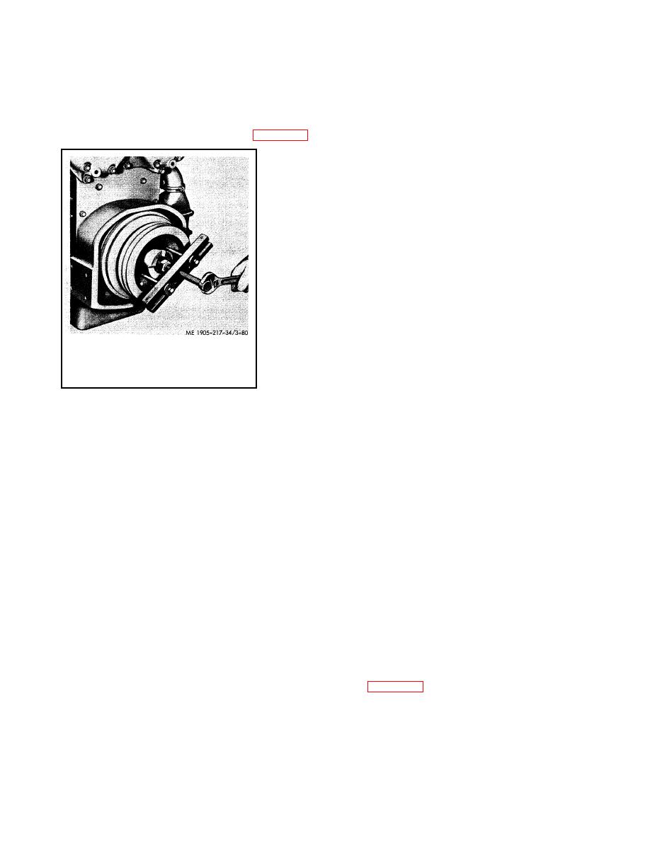
(3) Use a puller as shown in figure 3-80 to remove the pulley.
(4) Remove two damper-to-hub bolts and lock washers
diametrically opposite to each other.
(5) Reinstall the pulley crankshaft bolt and install a puller to
loosen the outer cone wedged between the crankshaft and the damper
hub. After loosening the cone it may be "fished" from the inner diameter of
the damper hub with two thin shank screw drivers.
(6) Slide the dampers with damper hub as an assembly off the
end of the crankshaft.
(7) Slide the inner cone from the crankshaft.
(8) Drill two holes directly opposite each other in the seal casing
and install metal screws with flat washers. Remove the seal by prying
against the flat-washers with suitable pry bars. 3-110
c. Cleaning. Clean damper and pulley with cleaning solvent (FED.
SPEC. PD-680) and dry thoroughly.
d. Inspection.
(1) Inspect the damper to see that the rubber is firmly bonded to
the metal parts at each side. If the damper has been exposed to solvent,
Figure 3-80. Crankshaft pulley, removal.
lubricating oil or excessive heat, the rubber may have become loosened
from the metal. In this event, the damper should be discarded and
replaced with a new one. Also, check to see that the metal discs are not bent.
(2) If damage to the vibration damper is extensive, inspect the crankshaft. A loose or defective vibration
damper, after extended operation, may result in a cracked crankshaft.
(3) Inspect the damper inner and outer cones, damper hub and the end of the crankshaft for galling or burrs.
Slight scratches or burrs may be removed with emery cloth. If seriously damaged, the parts should be replaced and the
end of the crankshaft refinished. Check the outside diameter of the inner cone for wear at the crankshaft front oil seal
contact surface. If worn, the oil seal and cone should be replaced.
e. Installation.
(1) There is a plastic coating on the outside diameter of the oil seal. Do not remove this coating.
(2) Apply grease to the sealing lip, then position the seal in front cover with the lip of the seal pointed toward the
inner face of the cover.
NOTE
The vibration damper inner cone must be removed before installing the oil seal.
(3) Drive the seal into the front cover with installer J 9783.
(4) Reinstall vibration dampers and crankshaft pulley in reverse order of removal, including inner and outer
cones.
(5) Tighten the crankshaft pulley retaining bolt to 290-310 ft-lb torque.
3-23. Transfer Gear Assembly
a. General. The hydraulic marine transfer gear is illustrated in figure 3-81. Power developed by the two engines is
delivered through the hydraulic marine gear system to the power drive gear (28), thence to the power driven gear (23)
power driven shaft (20). Power drive gear (28) is internally splined to receive the reverse gear drive shaft (3) and is
mounted on two ball bearings. The power drive gear bearing (front) (2) is carried in the reverse gear housing (1) power
drive gear bearing (rear) (27) is carried in the transfer gear housing (10).
3-10
|
||
 |
||