
| Tweet |

Custom Search
|
|

|
||
 TM 55-1905-221-14-4
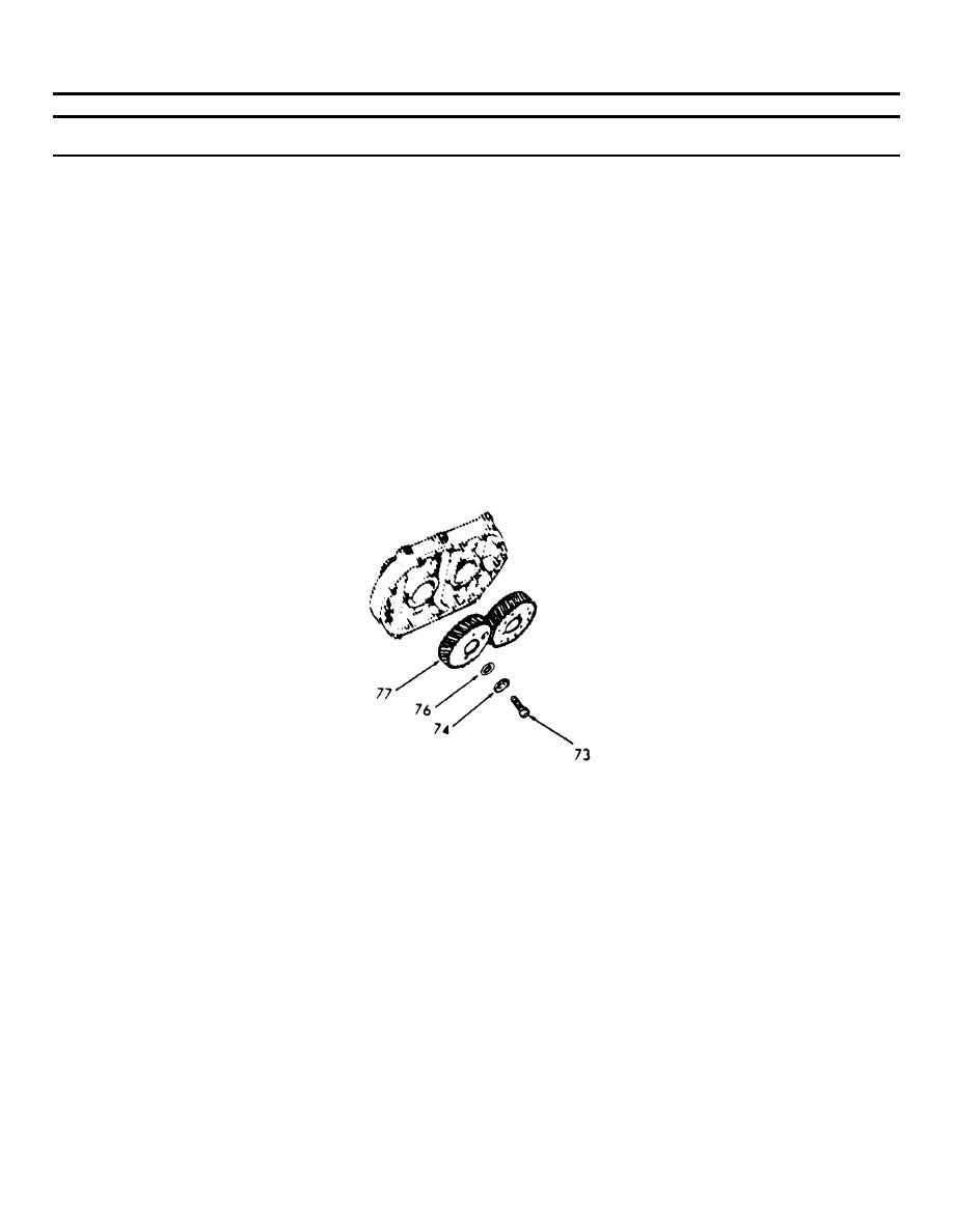
6-35. BLOWER ASSEMBLY (Continued).
LOCATION/ITEM
ACTION
REMARKS
REASSEMBLY (Cont)
(11) Place a key washer (74) and
the fuel pump drive coupling
disc (76) on the remaining
gear retaining capscrew (73).
Thread the capscrew (73) into
the left-hand helix rotor
shaft and guide the lugs on
the disc (76) in the slots in
the gear hub (77), then bend
one of the tangs on the key
washer (74) over the slot in
the disc (76). Tighten the
gear retaining capscrew to
55 - 65 ft-lb (74 - 88 Nm)
(12) Bend one of the tangs of each
key washer over against the
head of the gear retaining
capscrew.
44. Timing
a. After the blower rotors and timing
Rotors
gears are installed, the blower
rotors must be timed.
b. The blower rotors, when properly
positioned in the housing, run with
a slight clearance between the lobes.
This clearance may be varied by
moving one of the helical gears in
or out on the shaft relative to
the other gear.
6-686
|
||
|
||


