| Tweet |

Custom Search
|
|

|
||
 TM 55-1905-223-24-3
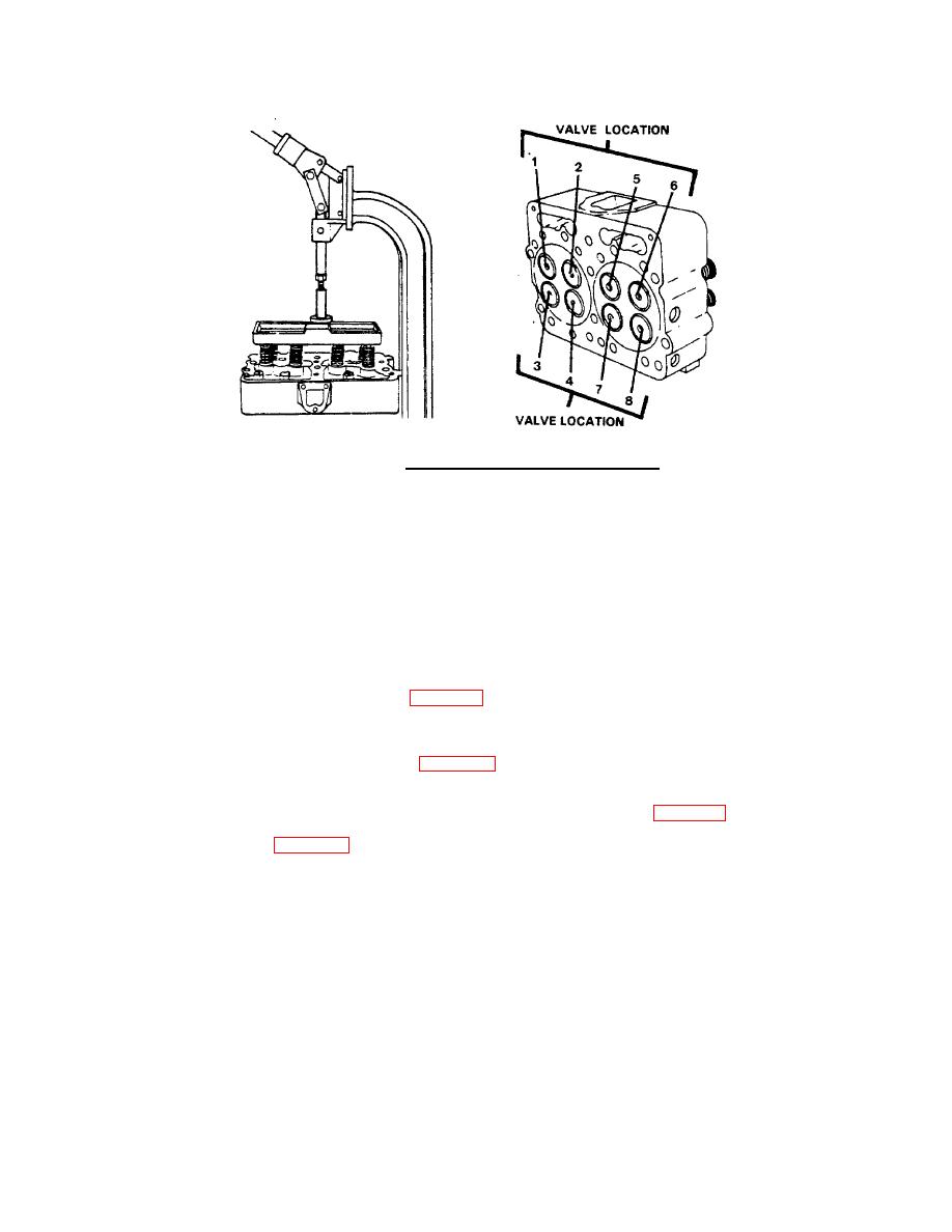
FIGURE 4-7. Removing and Marking Valves.
(1) Be sure that the valve spring compressor stand is fastened to the work bench.
(2) Align the center of the cylinder head with the plunger of the compressor stand.
(3) Position the compressor plate on the cylinder hea so the valve stems will be in the center of the holes in the
d
plate.
(4) Pull down the handle on the stand. Make sure the valve stems stay in the center of the holes.
(5) Bring the handle all the way down so the locking pin will engage the hole in the plunger. The locking pin holds the
plunger against the plate that compresses the springs.
(6) Remove the valve spring retainer locks (2, Figure 4-8).
(7) Push down on the stand handle and disengage the plunger. Raise the plunger from the cylinder ead.
h
(8) Remove the helical compression springs (1, Figure 4-8), helical compression spring seats (15, 3), and engine
poppet valves (9) from the cylinder head (10).
(9) Mark each valve as it is removed to identify its location in the cylinder head. See Figure 4-7.
d. Remove the pipe plug (12, Figure 4-8).
e. Remove the expansion plugs (5, 6, 7, and 11).
4-29
|
||
 |
||