| Tweet |

Custom Search
|
|

|
||
 TM 55-1905-223-24-5
NOTE
Do not press the pilot annular ball bearing (1) all the way onto the shaft. Room
must be left between the front face of the bearing inner race and the end of the
clutch shaft.
(1)
Press the pilot annular ball bearing (1) onto the clutch shaft (18) by applying pressure
to the inner race of the bearing.
(2)
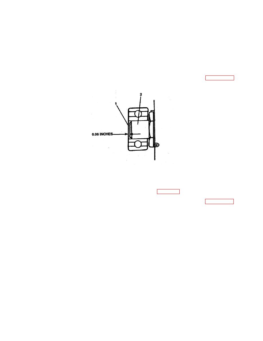
Leave a distance of 0.12 inch between the front face of the bearing (1, FIGURE 2-58)
inner race and the end of the clutch shaft (2).
FIGURE 2-58. Bearing End Clearance.
n.
Adjust clutch assembly as follows:
(1)
Install the friction, clutch assembly. Refer to para. 3-21.
(2)
With clutch disengaged, turn the clutch by turning the clutch shaft (18, FIGURE 2-57,
Sheet 1) until adjusting lock pin (29, Sheet 2) can be reached through a hand hole.
(3)
Depress lock pin (29) with a screwdriver and screw the adjusting ring (28) clockwise
one or two notches or until a distinct pressure is felt with the hand lever (20, Sheet 1).
(4)
Release adjusting pin (29, Sheet 2) and turn adjusting ring (28) to engage the nearest
notch with lock pin (29).
(5)
Engage and disengage the clutch a number of times with lever (20, Sheet 1) to check
operation. If a distinct pressure is not felt by lever (20) when operating, repeat steps
(1) through (4) until a distinct pressure is felt with hand lever (20, Sheet 1) when
engaging clutch.
2-160
|
||
 |
||