| Tweet |

Custom Search
|
|

|
||
 TM 55-1925-204-12
(b) Remove capscrews (35) and adapter
(2)
Removal.
(36), arm (6) and shaft (3).
(a) Remove capscrews securing header
(c) Remove nut from shaft (17), cam (18)
connections at cylinders and receiver, then remove header from
and sleeve (19).
the receiver, and connector (5, fig. 47) from line by uncoupling
flanges.
(d) Remove capscrews securing cover (25)
then remove cover (25) from gear (26). Remove gasket (24).
(b) Remove and discard gaskets (3 and 4).
(3) Cleaning, Inspection, and Repair.
(c) When necessary, remove covers from
housing then remove and discard gaskets (1 and 2).
(a) Clean all parts in clean fuel oil and blow
dry with ships service air.
(3) Cleaning, Inspection, and Repair.
(b) Inspect forward cam (18) and the reverse
(a) Wash all parts in clean fuel oil then wipe
cam attached for wear or rough lobes. Examine movement of
dry.
shaft (17). If there is end play in shaft, remove capscrews
(b) Be sure that all gasket material is
securing sleeve (29) and remove a shim (50) and a shim (31).
removed from surfaces to be gasketed.
Replace and secure sleeve (29), then try shaft end play.
(c) Inspect header sections for dirt, or
Removal of shims should have reduced end play by allowing
moisture residue.
bracket (30) to cause reversing mechanism to meet spool (33)
(4) Installation.
earlier, therefore reduce end play.
(a) Replace new gaskets (1 and 2), if
(c) If forward cam (18) or reverse cam
removed, then install covers.
attached is defective, separate the cams. Replace the defective
(b) Replace new gaskets (3) under header
cam (s).
sections at the receiver and tighten capscrews securing header
(4) Reassembly. Assemble the air distributor by
sections. Install new gaskets (4) at flanges of connector (5),
reversing the procedure in step (2) (a) through (d) above.
then bolt to header sections at both ends of connector.
(5) Installation.
Install
by
reversing
the
e. Air Receiver (BOX). The air receiver distributes air
procedures in step (1) (a) and (b) above.
from the scavenging pump to cylinders under the proper
d.
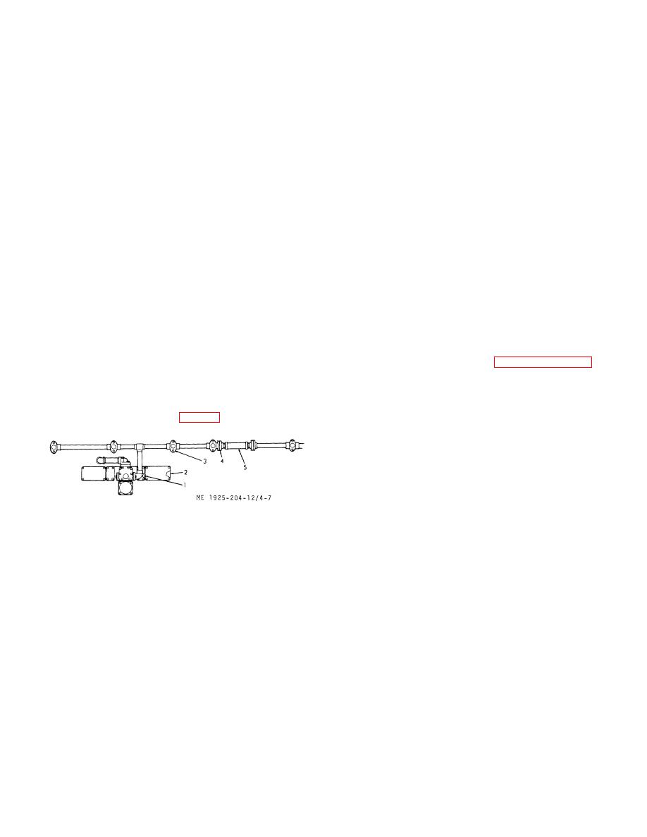
Air Start Header. The air start header is the piping
pressure (from 1 1/2 to 2 1/2 psi) for forcing exhaust gases out,
arrangement of air to cylinders for starting (reversing) the
and filling cylinder with combustion air.
engine. The principal maintenance requirement is to stop
leakage of air from header. When an air leak is suspected, test
remove the air receiver sections.
and correct.
(2) Cleaning, Inspection, and Repair.
(1) Testing. If a leak can not be felt by the fingers
(a) Wash the receiver parts in clean fuel oil
at joints, make up a solution of soap and water and apply at all
and wipe dry.
gasketed connections of header (fig. 4-7) at cylinders.
(b) Clean all gasket surfaces. Be sure that
all particles are removed, and the machined surfaces are
smooth.
(c) Inspect receiver for cracks, or other
damage. Replace a defective receiver section, or cover.
1. Gasket, housing cover
4. Gasket, pipe flange
2. Gasket, housing cover
5. Connector, air start header,
3. Gasket, receiver to header
flexible, with flanges
Figure 4-7. Air start header
4-15
|
||
 |
||