| Tweet |

Custom Search
|
|

|
||
 had been manually reset by pushing the button mounted on the
(2) Install mounting bolts; tighten only enough to
controller door.
hold motor firm.
(3) Align coupling half (para. 5-45 i. ).
b. Maintenance.
(4) Tighten mounting bolts and connect electrical
(1) Keep interior and exterior of inclosure clean.
wiring to motor.
(2) Inspect contacts for excessive burning or wear.
Smooth roughness from copper contacts with a fine file.
c. Removal.
5-47.
Motor Controller
(1) To remove the contactor from control panel, first
a. General. The controller is a magnetic type with current
remove fuses from fuse clips and disconnect electrical leads.
limit (two-step) acceleration. It is actuated by a START-STOP
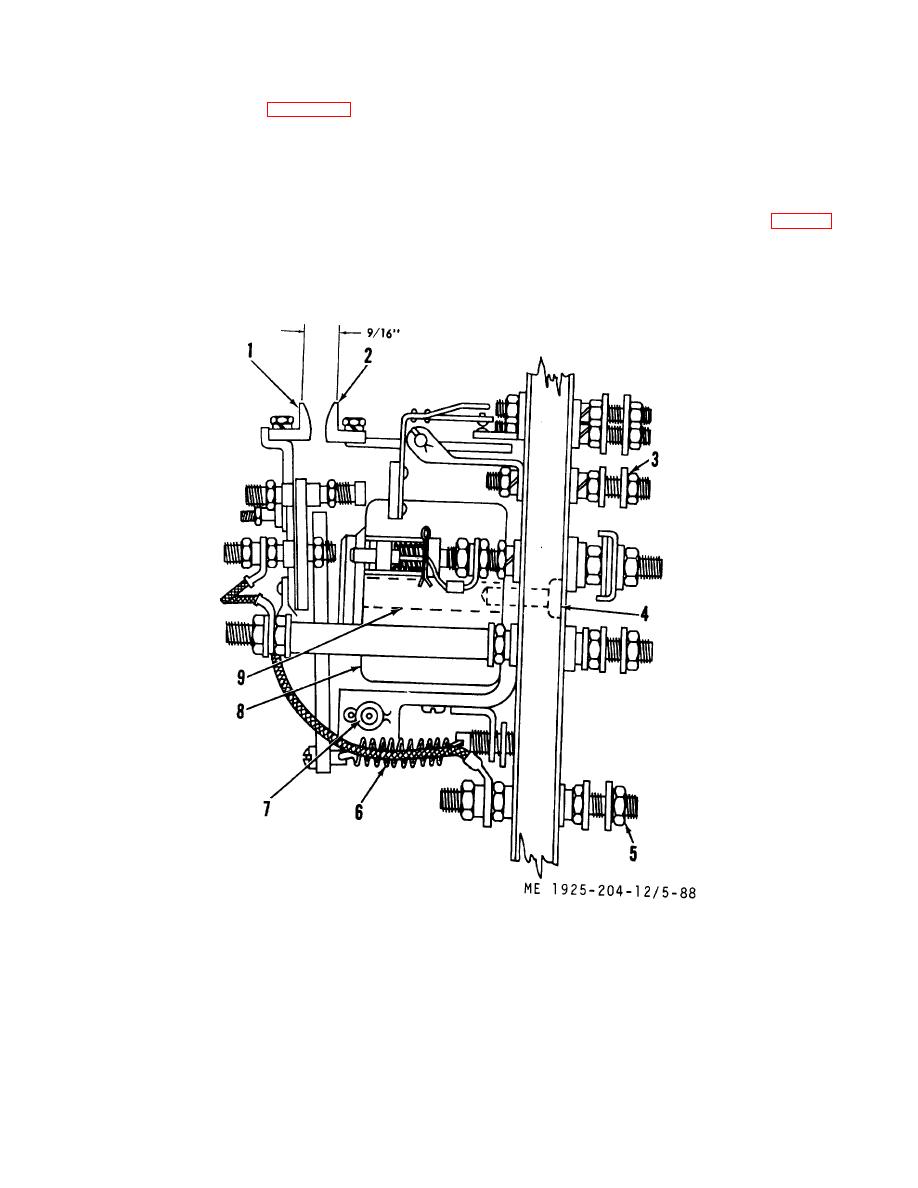
(2) Remove mounting bolts (3 and 5, fig. 5-88) that
selector switch mounted on the door of the controller inclosure.
hold contactor to controller panel and remove contactor from
Protection against overloads is furnished by the manually reset
controller.
overload relay, which opens its contacts when the current
reaches a predetermined percentage above normal, full-load
current. The motor cannot be restarted until the overload relay
1. Contact
4. Capscrew
7. Cotter pin and shaft
2. Contact
5. Mounting bolt
8. Coil
3. Mounting bolt
6. Spring
9. Core
Figure 5-88. Controller contactor.
5-118
|
||
 |
||