
| Tweet |

Custom Search
|
|

|
||
 TM 55-1905-217-12
c. Stabilized lubricating oil pressure is maintained
within the engine at all speeds, regardless of the oil
temperature, by means of a regulator valve located
between the pump outlet and the inlet to the cylinder
block. When the oil pressure at the valve exceeds 50
pounds per square inch, the regulator valve opens and
remains open until the pressure is less than -the opening
pressure.
4-24.
Engine Oil Filter
a. Description. This is a full-flow filter with a
replaceable element. A bypass valve, which opens at 15
psi, is located in the base.
b. Service. The element must be changed at every
oil change interval (100 hours). See figures 3-1 and 3-2.
c. Removal and Installation. Disconnect hoses,
then remove the filter from the bracket. Install in reverse
order of removal.
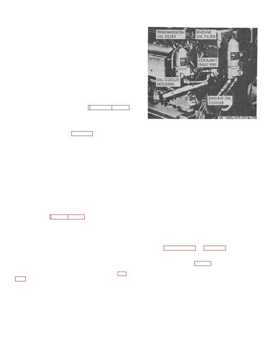
Figure 4-11. Engine oil cooler.
4-25.
Engine Oil Cooler (fig. 4-11)
b. Removal.
(1) Drain cooling system.
a. General. The oil cooler is located on the side of
(2) Remove coolant inlet pipe and outlet elbow.
the engine just below the water pump. To assure engine
(3) Remove oil cooler housing and the two
lubrication if the oil cooler becomes clogged, a bypass
elements.
valve located at the oil inlet to the cooler bypasses oil
c. Inspection of Oil Cooler.
around the cooler directly to the oil gallery in the cylinder
(1) Inspect the housing for damage, and
block. The core through which the oil passes while being
replace as necessary.
cooled is sealed to prevent a coolant from getting into the
(2) Inspect the two elements for excessive
oil. Whenever an oil cooler is assembled, special care
sludge buildup and damage, and replace as necessary.
must be taken to have the proper gaskets in place and
the retaining bolts tight.
SECTION X. ENGINE FUEL SYSTEM
with the hydrostarters to prevent accidental engagement
4-26. General
of the hydrostarter when the engine is running. Hulls
The fuel system (fig. 1-18 or 4-12) consists of the fuel
8540 thru 8560 and 8580 thru 8618 have fuel oil heat
tanks (2) and lines, fuel strainers (mounted aft on each
exchangers installed in the raw water cooling system.
propulsion unit), fuel pumps (driven from the blower
lower rotor shaft), fuel filters (mounted on the side of
4-27.
Engine Mounted Fuel Strainers and Fuel
each engine), fuel manifolds, and fuel injectors. Hull
numbers 8500 thru 8519 have an additional fuel strainer
Filters
for each propulsion unit. These strainers are mounted
Refer to paragraph 3-10 and figure 3-7 for daily service.
on the battery box. Hull numbers 8540 thru 8560 and
Every 500 hours clean strainer elements and replace
8580 thru 8618 incorporate a 2-psi relief valve in the
filter elements as follows:
return line. Additionally, these hull numbers include a
a. Fuel Strainers (fig. 3-7).
primary fuel strainer mounted on the aft bulkhead of the
(1) Disassembly.
engine room in the supply line from each reservoir (fig.
(a) Drain strainer body.
(b) Remove handle locknut and handle.
pressure switch interlocked
(c) Remove four nuts and washers from
clamping ring studs. Remove case and clamping
4-18
|
||
|
||


