
| Tweet |

Custom Search
|
|

|
||
 TM 55-1905-217-12
auxiliary terminal is higher than specified, field circuit is
(6) Stop engine and remove jumper wire
across auxiliary and field terminals. Connect a dc
defective-check brushes. If voltage reads 0 volts at
auxiliary terminal, check field excitation device and
ammeter across field and positive output terminals (fig.
associated circuit. If voltage is not correct, perform test
in (6) below.
disconnected). Current should be 1.5 to 2.0 amperes.
Disassemble and repair alternator if current is excessive
or low.
NOTE
c. In-Vessel Testing (Hull numbers 8540 thru 8560
Disconnect jumper wire after testing.
and 8580 thru 8618.)
(1) Hull numbers 8540 thru 8560 and 8580
(3) With propulsion unit or engine running,
thru 8618 contain a revised model of the 70-amp, 24-volt
check voltage across auxiliary and negative output
alternator. This model differs from the previous model
voltage is 29.4 0.2 volts. If voltage is low, proceed with
due to the replacement of the isolation diode with a field
diode assembly. The assembly consists of three rectifier
tests.
diodes, mounted on a common heat sink, electrically
(4) With engine running, check voltage across
connected in parallel with the conventional positive
positive and negative output terminals (fig. 4-41.1) with
rectifier diodes. After initial alternator excitation utilizing
dc voltmeter. Correct voltage at positive output terminal
battery energy, the field diode assembly provides the
is 1.0 volt less than voltage in (3) above. If voltage
continuing energy requirement. A new voltage regulator
difference exceeds 1.0 volt, isolation diode is defective.
is used in conjunction with the new alternator. The new
(5) Stop engine and disconnect voltage
regulator is similar to the previous model but operates
regulator (fig. 4-41.2). Place jumper wire across
the field at a one-volt lower value. Figure 4-41.4 is a
auxiliary and field terminals. With engine-running at idle,
schematic of the alternator system. The following test
check voltage across auxiliary and negative output
terminals. Correct voltage is 29.4 0.2 volts. If voltage
equipment is required to conduct the in-vessel alternator
system checks:
was low in (3) above and now rises to correct voltage,
regulator is defective and shall be replaced. If voltage
remains low, alternator is defective.
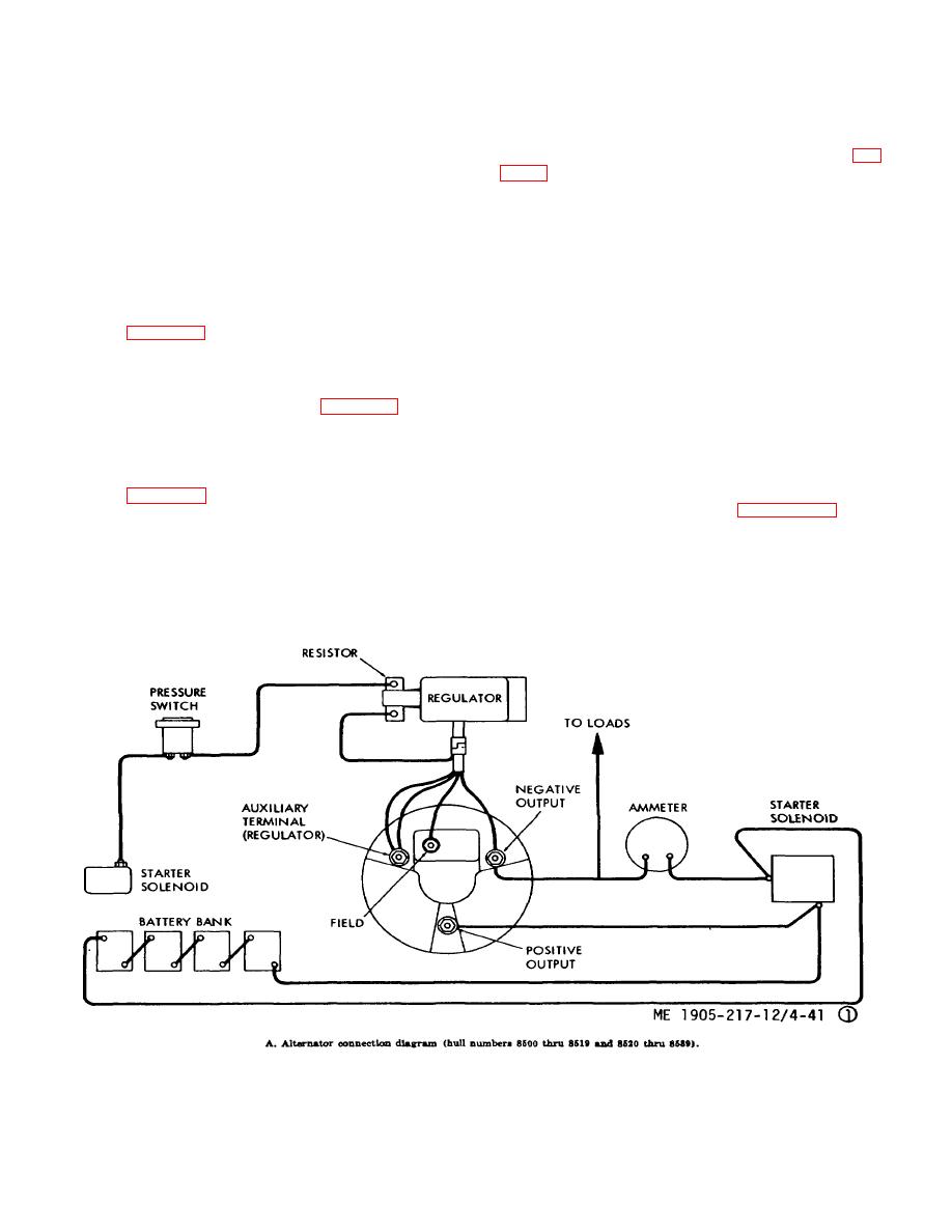
Figure 4-41.1. Alternator testing.(Sheet 1 of 8)
4-44
|
||
|
||


