| Tweet |

Custom Search
|
|

|
||
 TM 55-1905-223-24-5
(2)
Tighten two 7/16 inch capscrews on each side of the oil pan flange halfway between
the front and the rear of the oil pan.
(3)
Remove the capscrews that were installed in step c.(l) of this procedure. This is
necessary to provide the clearance to perform the following step.
(4)
Install and tighten four 5/16 inch capscrews in the rear of the oil pan
(5)
Install and tighten 28 7/16 inch capscrews in the remaining oil pan capscrew holes.
(6)
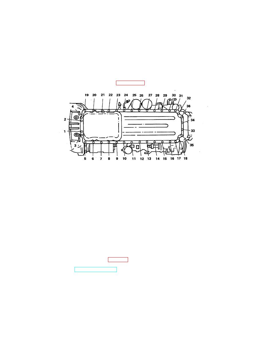
Torque the 5/16 inch capscrews to 20 ft-lb and the 7/16 inch capscrews to 50 ft-lb in
the sequence shown in FIGURE 2-61 .
FIGURE 2-61. Oil Pan Capscrews Torque Sequence.
(7)
Tighten the capscrews that hold the oil pan buttress to the flywheel housing the 70-80
ft-lb torque.
d.
Install the flange to tube elbow connection (11) and gasket (12) in the oil pan.
e.
Connect nonmetallic hose assembly (14) to the oil pan and lubricating oil pump flange to tube elbow
(11) and tighten.
f.
Use a gasket (19) and install the hand hold cover (18) and oil gauge (dipstick) tube (20). Tighten the
capscrews (16) to 30 to 35 ft-lb torque.
g.
Install the support clip (15) to the nonmetallic hose assembly (14).
h.
Place dipstick (21) into the oil gauge tube (20).
i.
Fill the engine with clean oil (PMCS Table 2-1, Item 12).
j.
Operate the engine (TM 55-1905-223-10) until the water temperature reaches 180 (80 ), and check
F
C
for oil leaks. Repair as necessary.
k.
Remove "Out of Service - Do Not Operate" tag.
2-164
|
||
 |
||