| Tweet |

Custom Search
|
|

|
||
 TM 55-1905-242-14
UNIT MAINTENANCE
FOR LANDING CRAFT, MECHANIZED (LCM-8) (ALL VESSELS WITH MOD 2 APPLICATION)
HYDRAULIC GAUGES, RUDDER ANGLE INDICATOR, AND AMMETER, REPLACE
INITIAL SETUP:
Tools and Special Tools:
Materials/Parts:
Tool Kit, Mechanic's Rail and Marine
Gloves, Chemical Protective (Item 3, Table 2, WP 0230 00)
(Item 1, Table 1, WP 0230 00)
Goggles, Industrial, No Vents (Item 4, Table 2,
Multimeter (Item 2, Table 1, WP 0230 00)
Suitable Drain Pan
Rag, Wiping (Item 5, Table 2, WP 0230 00)
Equipment Condition:
References:
Battery isolation switches set to OFF, locked out,
FM 55-502
and tagged out IAW FM 55-502
TM 55-1905-242-24P (WP 0008)
Personnel Required:
Two Watercraft Engineers, 88L
REMOVAL--RUDDER ANGLE INDICATOR
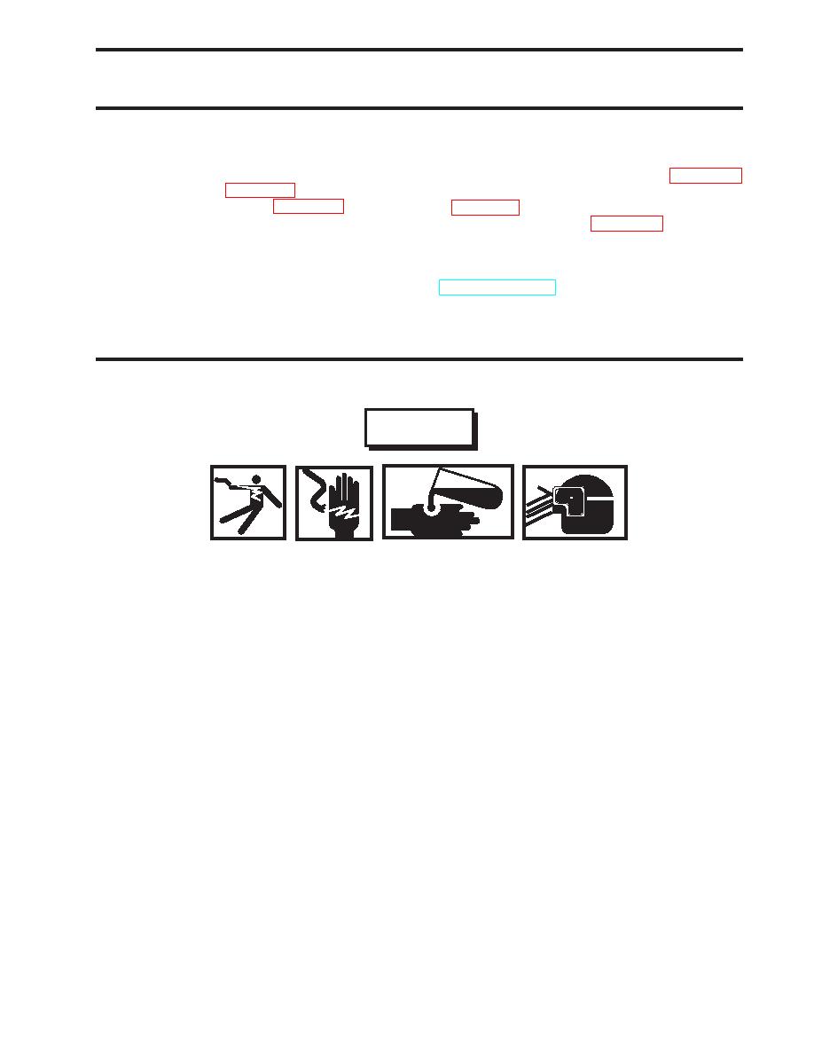
WARNING
Replace or repair components only after the affected circuit has been secured, locked
out, and tagged out. Performing replacement with the circuit energized may result in
damaged equipment and serious injury or death to personnel.
Do not allow hydraulic fluid or cleaning solvent to come in contact with unprotected
skin or eyes. Prolonged skin contact can cause illness or injury. Eye contact can cause
serious injury. Always wear chemical protective gloves and goggles when handling
used hydraulic fluid and cleaning solvent. Failure to comply can result in illness, seri-
ous injury, or death.
Hydraulic hoses and lines may be under pressure. Relieve pressure by operating the
appropriate control valve if possible. Loosen fittings on hose lines slowly. Allow oil to
run around threads of fitting, releasing pressure before disconnecting fitting. Releasing
pressurized oil suddenly can cause serious injury or death.
1.
Remove the screws (1) that attach the gauge panel (2) to the console (3) and lift the gauge panel away from the console.
2.
Set the multimeter to the Vdc (Volts direct current) setting and check for voltage on all of the gauges. If no voltage is
noted, proceed to the next step. If voltage is noted, ensure that the system is properly secured, locked out, and tagged
out.
3.
Label and disconnect the wiring (4) from the back of the gauge (5).
4.
Remove the screws (6) that attach the gauge (5) to the gauge panel (2).
0080 00-1
|
||
 |
||