
TM 5-3990-264-13&P
0030
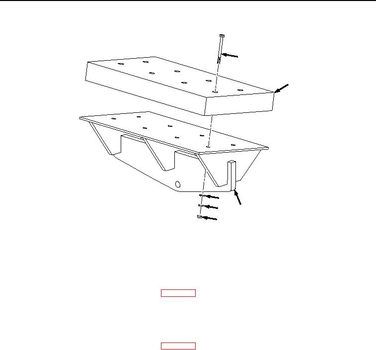
REMOVAL - Continued
17
18
16
15
19
14
Figure 2.
Guide Pad Removal.
END OF TASK
CLEANING
Refer to General Maintenance Instructions (WP 0017) for general cleaning instructions.
END OF TASK
INSPECTION
Refer to General Maintenance Instructions (WP 0017) for general inspection instructions.
END OF TASK
INSTALLATION
NOTE
Left and right front guide pad assemblies are installed the same way. Left side shown.
Install brackets as noted prior to removal.
1.
Install contact guide pad (Figure 3, Item 18) on contact guide pad mount (Figure 3, Item 19) with eight screws
(Figure 3, Item 17), washers (Figure 3, Item 16), lockwashers (Figure 3, Item 15), and nuts (Figure 3, Item 14).
03/15/2011Rel(1.8)root(maintwp)wpno(M06018)