TM 5-3990-264-13&P
0017
GENERAL WELDING MAINTENANCE - Continued
Weldment Points - Continued
7
7
3
1
4
7 7
4
5
4
4
4
2
5
6
3
1
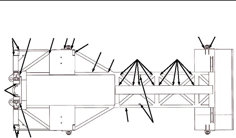
Figure 1.
Top View
3.
CORNER FITTING AND ADJACENT STRUCTURE (Figure 1, Item 3). Due to the high loads that these fittings
can see in a transport mode, the crack should be repaired before reaching 1/2 inch (1 cm) in length. The
combined length of multiple cracks at any one location should not exceed 1/2 inch (1 cm). This applies to
cracks present in the adjoining structure also.
4.
CROSS MEMBERS (Figure 1, Item 4). These welds are located at the junction of the crossmember and the
main rails. A crack should be repaired before it has reached 2 inches (5.08 cm) at one location. The total length
of all cracks on a single crossmember should not exceed 2 inches (5.08 cm). When cracks are present on
several cross members, action should be taken to repair it at the next service. If a crossmember is completely
missing, repairs should be made prior to use.
5.
MAIN RAILS (Figure 1, Item 5). The main rails provide a major portion of the load carrying capacity of the IBC.
They support a portion of the load while loaded on the CBT and PLS trailer. Cracks in the main rail should be
repaired before reaching 1 inch (2.54 cm).
6.
LOCKING TABS (Figure 1, Item 6). The locking tabs are used to secure the IBC to the CBT and PLS trailer.
Due to the high loads that these tabs can see in the transport mode, a crack should be repaired before reaching
1/2 inch (1.27 cm) in length.
7.
STANCHION POCKETS (Figure 1, Item 7). The stanchion pockets are used to secure stanchion poles to IBC
during bridge erection boat retrieval. A crack should be repaired before it has reached 2 inches (5.08 cm). The
combined length of multiple cracks at any one location should not exceed 4 inches (10.16 cm).
03/15/2011Rel(1.8)root(maintwp)wpno(M06000)

