
TM 5-3990-264-13&P
0027
ASSEMBLY - Continued
5
4
5
5
4
5
10
1
9
7
3
8
6
3
2
6
11
18
17
20
12
21
17
14
16
19
15
23
21
12
13
22
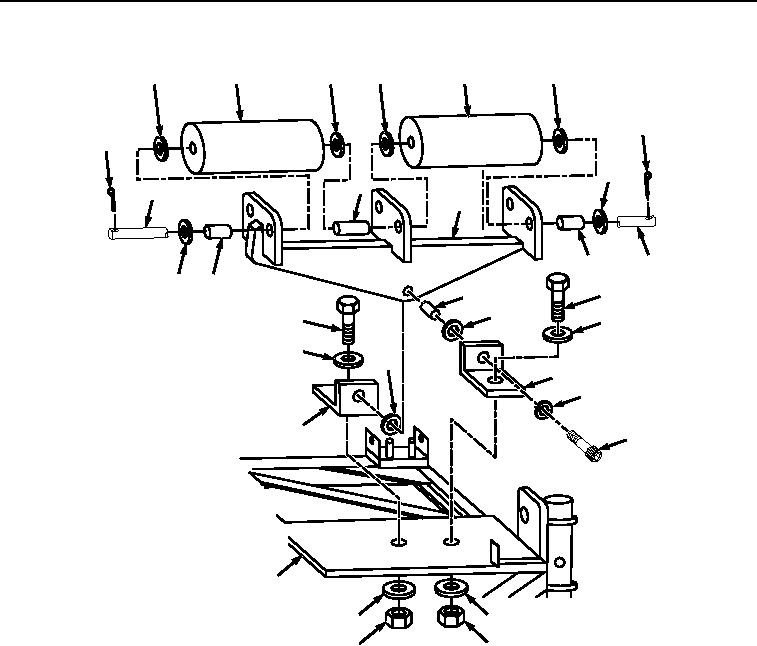
Figure 2.
Front Roller Assembly.
2.
Install roller bracket (Figure 2, Item 8) to inboard threaded angle bracket (Figure 2, Item 19) with two thrust
washers (Figure 2, Item 17), bearing sleeve (Figure 2, Item 18), outboard non-threaded angle bracket (Figure
2, Item 14) lockwasher (Figure 2, Item 16), and shoulder screw (Figure 2, Item 15).
3.
Install outboard non-threaded angle bracket (Figure 2, Item 14) to IBC frame (Figure 2, Item 23) with capscrew
(Figure 2, Item 11) two washers (Figure 2, Item 12), and locknut (Figure 2, Item 13).
4.
Install cotter pin (Figure 2, Item 10) and washer (Figure 2, Item 9) to shaft (Figure 2, Item 3).
5.
With the aid of an assistant, install two rollers, Figure 2, Item 4), four washers (Figure 2, Item 5), two bearing
sleeves (Figure 2, Item 6), and spacer (Figure 2, Item 7) to roller bracket (Figure 2, Item 8) with shaft (Figure
2, Item 3).
6.
Install washer (Figure 2, Item 2) and cotter pin (Figure 2, Item 1) to shaft (Figure 2, Item 3).
7.
Repeat Steps (4) through (6) if other set of rollers were removed.
END OF TASK
03/15/2011Rel(1.8)root(maintwp)wpno(M06011)