
TM 5-3990-264-13&P
0028
DISASSEMBLY - Continued
6
5
7
8
2
1
3
4
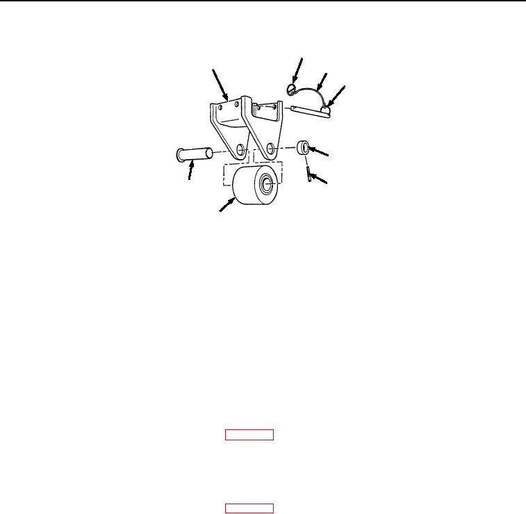
Figure 2.
Roller Disassembly.
2.
Remove collar (Figure 2, Item 2), headed straight pin (Figure 2, Item 3), and solid wheel (Figure 2, Item 4) from
bracket (Figure 2, Item 5).
NOTE
Perform Steps (3) and (4) if straight pin assemblies are damaged.
3.
Spread ring pin (Figure 2, Item 6) apart and remove from wire rope (Figure 2, Item 7).
4.
Remove wire rope (Figure 2, Item 7) from retaining ring (Figure 2, Item 8). Discard wire rope.
END OF TASK
CLEANING
Refer to General Maintenance Instructions (WP 0017) for general cleaning instructions.
END OF TASK
INSPECTION
Refer to General Maintenance Instructions (WP 0017) for general inspection instructions.
END OF TASK
ASSEMBLY
NOTE
Both left and right IBC roller assemblies are assembled the same way. Right side is shown.
1.
Install solid wheel (Figure 3, Item 4) in bracket (Figure 3, Item 5) with headed straight pin (Figure 3, Item 3).
03/15/2011Rel(1.8)root(maintwp)wpno(M06012)