TM 5-1940-321-13&P
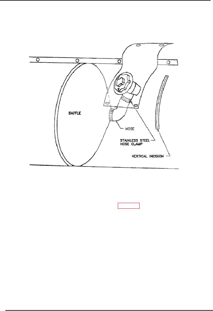
Figure 7-15. Location of the Incision to Replace an Intercommunicating Valve.
( 4 ) Remove the valve base nut shown in figure 7-16 using the half-moon spanner.
Using an indelible ink marking pen, draw a straight line on the metal valve body
and the buoyancy tube fabric. These lines will be used during reassembly to
correctly position the new valve. Allow the valve to drop into the buoyancy tube.
( 5 ) Using an indelible marker, mark the position of the hose and the valve hose
connection on the buoyancy tube fabric to assist in precisely locating the new valve
in the same position. Also mark a line on the hose and the valve to assist in
relocating the hose on the new valve. Do not damage or cut the hose. This repair
cannot be completed if the hose is damaged.
7-24

