
TM 5-3990-264-13&P
FIELD MAINTENANCE
LOAD BINDER CABLE ASSEMBLY REPLACEMENT
INITIAL SETUP:
Equipment Condition
Tools and Special Tools
Tool Kit, General Mechanic's: Automotive
Bridge erection boat installed on IBC. (WP 0007)
(WP 0044, Table 2, Item 2)
References
Parts Manual (WP 0039, Figure 4)
REMOVAL
NOTE
Both left and right load binder cable assemblies are removed the same way. Left side is
shown.
1.
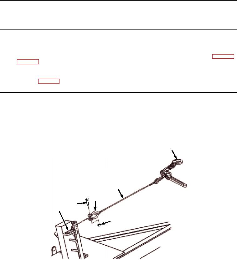
Unhook eye hook (Figure 1, Item 1) from bridge erection boat.
1
5
4
2
6
3
Figure 1. Load Binder Removal.
2.
Remove bolt (Figure 1, Item 2) and nut (Figure 1, Item 3) from chain shackle (Figure 1, Item 4).
3.
Remove load binder (Figure 1, Item 5) and chain shackle (Figure 1, Item 4) from IBC frame (Figure 1, Item 6).
END OF TASK
03/15/2011Rel(1.8)root(maintwp)wpno(M06003)