
TM 5-3990-264-13&P
FIELD MAINTENANCE
FRONT AND REAR TIE-DOWN CABLE REPLACEMENT
INITIAL SETUP:
References
Equipment Condition
Parts Manual (WP 0039, Figure 5)
Bridge erection boat installed on IBC. (WP 0004)
REMOVAL
NOTE
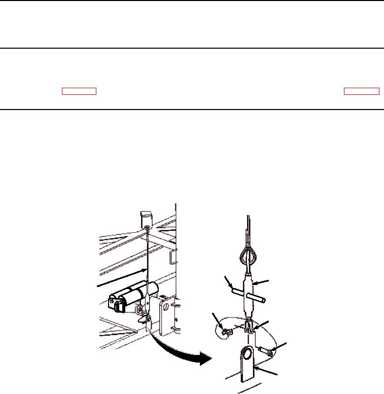
Both the front (shortest) and rear (longest) tie-down cables are removed the same way. Front
tie-down cable is shown.
1.
Turn handle (Figure 1, Item 1) to loosen turnbuckle (Figure 1, Item 2) until pressure is relieved from pin (Figure
1, Item 3).
1
2
7
4
5
3
6
Figure 1.
Tie Down Cable Removal.
2.
Remove ring pin (Figure 1, Item 4) and pin (Figure 1, Item 3) from turnbuckle jaw (Figure 1, Item 5) and IBC
frame (Figure 1, Item 6).
3.
Remove front tie-down cable assembly (Figure 1, Item 7) from bridge erection boat.
4.
Store front and rear tie-down cable assembly (Figure 1, Item 7) in bridge erection boat.
END OF TASK
03/15/2011Rel(1.8)root(maintwp)wpno(M06004)