
TM 5-3990-264-13&P
FIELD MAINTENANCE
STANCHION PIN REPAIR
INITIAL SETUP:
References (cont.)
Tools and Special Tools
Tool Kit, General Mechanic's: Automotive
(WP 0044, Table 2, Item 2)
Parts Manual (WP 0039, Figure 1)
Materials/Parts
Equipment Condition
Wire Rope, 12463607-12 (WP 0035)
IBC on vehicle (WP 0004), IBC on PLS trailer
Wire Rope, 12463607-16 (WP 0035)
(WP 0008), or IBC on level ground
Bridge erection boat removed from IBC.
References
REMOVAL
NOTE
All four stanchion pins are removed the same way. Left side is shown.
1.
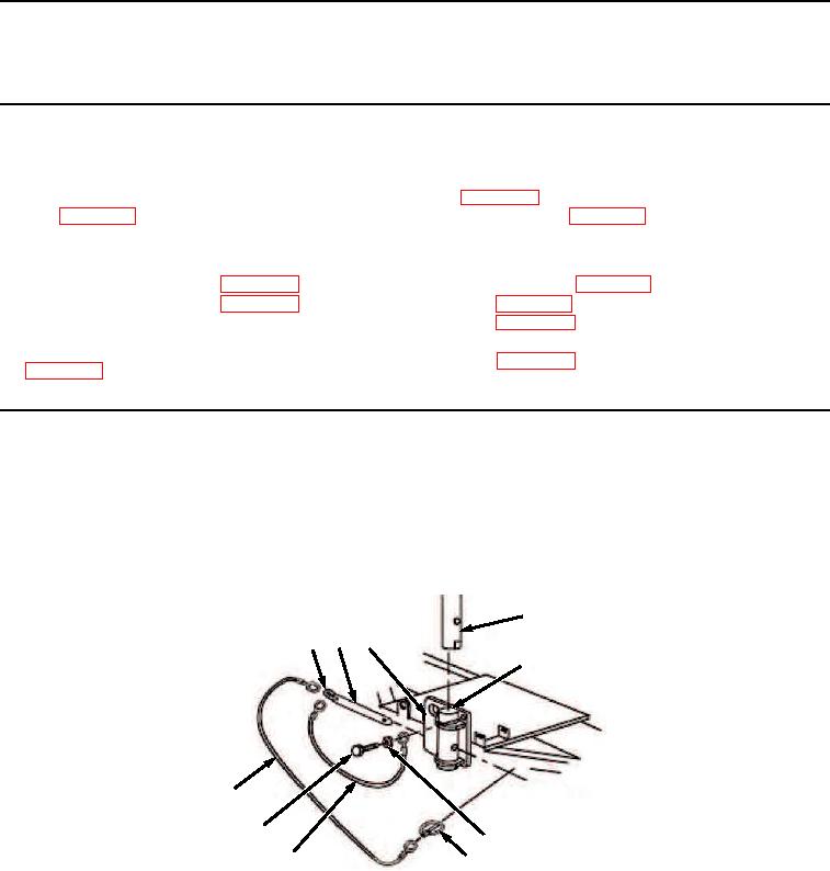
Remove self-tapping screw (Figure 1, Item 1), flat washer (Figure 1, Item 2), and wire rope (Figure 1, Item 3)
from cradle frame (Figure 1, Item 4).
7
10 6
4
8
9
1
2
5
3
Figure 1. Pin Removal.
2.
Remove ring pin (Figure 1, Item 5) from headless straight pin (Figure 1, Item 6).
3.
Holding stanchion (Figure 1, Item 7) in place, remove headless straight pin (Figure 1, Item 6) from stanchion
pocket (Figure 1, Item 8).
END OF TASK
03/15/2011Rel(1.8)root(maintwp)wpno(M06006)